Can you squeeze in two more locations in series with D4 & D5?
These two extra locations can be two more LEDs, or a LED + fixed resistor, or a LED + Zener, or fixed resistor + Zener.
Basically, you want VR (P1) to be as low as possible for best performance.
These two extra locations can be two more LEDs, or a LED + fixed resistor, or a LED + Zener, or fixed resistor + Zener.
Basically, you want VR (P1) to be as low as possible for best performance.
Hi Salas,
thanks for your fast response. c4 and c5 in my schematic should be 220uF not the 1mF as shown in the schematic. you advise 47uF for C5 and for C4 ( both elekrolytics) and delete R3,R4 they are only necessarily for 9240?
thanks for your fast response. c4 and c5 in my schematic should be 220uF not the 1mF as shown in the schematic. you advise 47uF for C5 and for C4 ( both elekrolytics) and delete R3,R4 they are only necessarily for 9240?
Yes.
The only item I think worth raising is that T1 & T3 do not need to be k170 or similar high gm, low pinch off devices.
T1 & T3 can be any jFET based CCS device, when output voltage is >=5V.
The only item I think worth raising is that T1 & T3 do not need to be k170 or similar high gm, low pinch off devices.
T1 & T3 can be any jFET based CCS device, when output voltage is >=5V.
k117 falls into the same category as k170.
Difficult to source, expensive, high gm, low pinch off.
244, 245, and many others with lower gm and higher pinch off are available at much lower cost.
Difficult to source, expensive, high gm, low pinch off.
244, 245, and many others with lower gm and higher pinch off are available at much lower cost.
Hi Salas,
thanks for your fast response. c4 and c5 in my schematic should be 220uF not the 1mF as shown in the schematic. you advise 47uF for C5 and for C4 ( both elekrolytics) and delete R3,R4 they are only necessarily for 9240?
I had run a spice sim for your available parts shown and what I advised gave the smoothest curves. Just do the revised schematic you posted without semi or value changes.
P.S. With 9610 you will need a 4th LED if you will try run more than about 250mA CCS. It will help you with voltage margin for sensible R1 values.
thanks!
caps have been removed as adviced. Unfortunately do not have any scope, planning to get one in the following month...
what could that be?!
Salas
Is that correct - your shunt PS got to have no local decouple caps on load
Salas
Is that correct - your shunt PS got to have no local decouple caps on load
Better not if you can't scope. Type and position can create a problem or not.
thank you for reply
what to look at with scope - ripple with / without decouple cap
what do you recommend as a value of load decouple cap - always lower than shunt V out cap or not If we power supply dac chip or line amplifier
what to look at with scope - ripple with / without decouple cap
what do you recommend as a value of load decouple cap - always lower than shunt V out cap or not If we power supply dac chip or line amplifier
You engage AC input on scope. You set the horizontal (time button) at 20-50us. You set your vertical button at 5-10mV. You hook up the probe on power rail, crock clip at nearest ground. You look for a straight line outcome, no sinus or weird patterns, no thick noise fuzz.
Can't recommend for load decoupling in general, there are very specific needs many times. But solid tantalum 10uF or 22uF local capacitors did show good overall rail in some reported reg-load combinations.
Can't recommend for load decoupling in general, there are very specific needs many times. But solid tantalum 10uF or 22uF local capacitors did show good overall rail in some reported reg-load combinations.
"KISS" v1.0 18V prototype
Hi 🙂
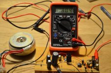
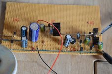
I build a v1.0 18V prototype, main purpose is to power a couple of B1's (not symmetric).
I changed a couple of things:
1) CCS I = 100mA (R1=6,2)
2) Used TL431 for Vref
3) Used IRF9610 for FETs
The thing is powered from a 10VAC toroidal that I salvaged from an old traffic light 😉 giving me some 25,5VDC; see attached schematic (from Eagle).
Schematic intentionally illustrates the components "placement" in the breadboarded prototype.
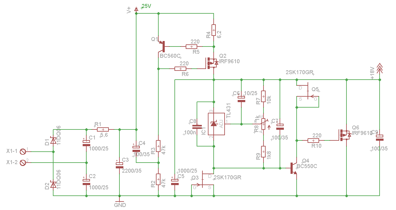
Initially I was having issues with the CCS as the current would decrease when input voltage (from lab psu) rose above some 21-22V, getting as low as 60mA at about 29V in.
Not good as it also hurt the performance of the shunt - set at 18,04V it decreased to below 18V when Vin got over 29V...
I therefore changed the current through the current sensing BJT by changing the 4k7 resistors to 47k.
Then it works nicely to atleast 35V in 🙂
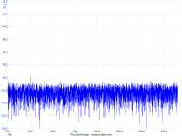
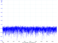
According to my PicoScope the noise is well below -92dBu, only a spike hitting -92dBu at 50Hz - I'm amazed!!
Now I wanted a KISS shunt, and the TL431 does not really makes things easier. I do not fancy remote sensing as 1) it's not KISS 2) if not done properly you can end up introducing more issues than you try to solve. I suggest using high-quality caps close to power-need instead.
So, I'll experiment with some variations over v1.0 and eventually actually listening to it on my friends B1 ;-)
Hi 🙂
I build a v1.0 18V prototype, main purpose is to power a couple of B1's (not symmetric).
I changed a couple of things:
1) CCS I = 100mA (R1=6,2)
2) Used TL431 for Vref
3) Used IRF9610 for FETs
The thing is powered from a 10VAC toroidal that I salvaged from an old traffic light 😉 giving me some 25,5VDC; see attached schematic (from Eagle).
Schematic intentionally illustrates the components "placement" in the breadboarded prototype.
Initially I was having issues with the CCS as the current would decrease when input voltage (from lab psu) rose above some 21-22V, getting as low as 60mA at about 29V in.
Not good as it also hurt the performance of the shunt - set at 18,04V it decreased to below 18V when Vin got over 29V...
I therefore changed the current through the current sensing BJT by changing the 4k7 resistors to 47k.
Then it works nicely to atleast 35V in 🙂
According to my PicoScope the noise is well below -92dBu, only a spike hitting -92dBu at 50Hz - I'm amazed!!
Now I wanted a KISS shunt, and the TL431 does not really makes things easier. I do not fancy remote sensing as 1) it's not KISS 2) if not done properly you can end up introducing more issues than you try to solve. I suggest using high-quality caps close to power-need instead.
So, I'll experiment with some variations over v1.0 and eventually actually listening to it on my friends B1 ;-)
Attachments

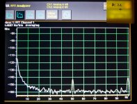
TL431 is still rather noisy for Vref IMHO, make your C7 a 1000uF cap and see if it lowers the FFT noise floor. Here is a member's measurement from Mezmerize DCB1's shunt reg rail with LEDS Vref and 100uf filtering. 0dbu=0.775VRMS. Don't know if the ref level was set otherwise than 0dbu though.
Attachments
Hi, thanks, yes, I know.
And it's no longer KISS with all the "support Rs, Cs".
I was considering a string of blue LEDs until I a couple of 100's pages back read they are too noisy too ;-)
Will probably go with a string of red LEDs or just a single resistor.
I'll get back 🙂
And it's no longer KISS with all the "support Rs, Cs".
I was considering a string of blue LEDs until I a couple of 100's pages back read they are too noisy too ;-)
Will probably go with a string of red LEDs or just a single resistor.
I'll get back 🙂
P.S. Is the second picture representing your Picoscope self noise floor limit?
Yes, I think so. Just for sanity I measured the lab PSU and it was about 12dB above, with clear spikes at 50, 100 and 300Hz...
Edit: It is actually measured at output of the prototype, but I think the noise is just below/on level with my scope... Quite amazing giving the circumstances 🙂
Last edited:
Yes, I think so. Just for sanity I measured the lab PSU and it was about 12dB above, with clear spikes at 50, 100 and 300Hz...
So you know you at least hit your test gear floor level apart from a bit of hum pick up (move that toroid a bit). OTOH you don't know if you really are even below. What lab PSU model?
- Status
- Not open for further replies.
- Home
- Amplifiers
- Power Supplies
- The simplistic Salas low voltage shunt regulator