The easiest way: DMM set for 2kohms. Probe between all legs (i.e. 1 and 2, 1 and 3, 2 and 3) Repeat inverting polarity (if you put the red probe on leg 1 and black on leg 3, invert them: red on 3 and black on 1).
Eventually compare with a new one, but if there is one short, it's gone. Replace.
Grazie mille (thks a lot).
Questo test serve anche per tutti i BJT, vero? (this test is ok for all BJT, ok?)
A presto, (see you soon)
The easiest way: DMM set for 2kohms. Probe between all legs (i.e. 1 and 2, 1 and 3, 2 and 3) Repeat inverting polarity (if you put the red probe on leg 1 and black on leg 3, invert them: red on 3 and black on 1).
Eventually compare with a new one, but if there is one short, it's gone. Replace.
When you say "short" are you refering that DVM set for 2K are reading some value, right?
Yes. It's not formally correct method (Andrew might kill me), but good for dummies 😉
Short = 0.000
I checked right now an IRFP140 (working): the lowest value 170 ohms, most measures give over 2K thus no indication on DMM.
P.S. your Italian is better than my English!
Short = 0.000
I checked right now an IRFP140 (working): the lowest value 170 ohms, most measures give over 2K thus no indication on DMM.
P.S. your Italian is better than my English!
Last edited:
Yes. It's not formally correct method (Andrew might kill me), but good for dummies 😉
Short = 0.000
I checked right now an IRFP140 (working): the lowest value 170 ohms, most measures give over 2K thus no indication on DMM.
P.S. your Italian is better than my English!
Grazie di nuovo massimo, adesso tutto chiaro e a posto. (thks again, now all clear & ok)
Mine Italian is better than mine English too.
I tested all IRPF 9140 used in the regs. & all aren't short no read (.OL) any value with DMM set for 2kohms.😕
Have a look at this page, on how to test the bipolars and the mosfet.
MOSFET testing
Testing semiconductors with analog and digital multimeters
A simple test is usually enough to show problems.
Do you know what is the Vf of your LEDs? R1 should be roughly equal to (3 x Vf) / desired_current. So for testing, if your LEDs have Vf = 1.8V or even Vf = 2.1V, and we're aiming for something around 20mA, then you can use R1 = 300R.
For 1.8V LED
I = 3 * 1.8 / 300 = 18 mA
For 2.1V LED
I = 3 * 2.1 / 300 = 21 mA
The 300R resistor can be 1/2W or whatever you have around.
You will know it works well if you measure the voltage across R1 and divide it by 300 and if the result is close to about 20. Of course you should see the LEDs on.
Try to implement just the CCS portion with a 300R for R1.
Have a look at this page, on how to test the bipolars and the mosfet.
MOSFET testing
Testing semiconductors with analog and digital multimeters
A simple test is usually enough to show problems.
Do you know what is the Vf of your LEDs? R1 should be roughly equal to (3 x Vf) / desired_current. So for testing, if your LEDs have Vf = 1.8V or even Vf = 2.1V, and we're aiming for something around 20mA, then you can use R1 = 300R.
For 1.8V LED
I = 3 * 1.8 / 300 = 18 mA
For 2.1V LED
I = 3 * 2.1 / 300 = 21 mA
The 300R resistor can be 1/2W or whatever you have around.
You will know it works well if you measure the voltage across R1 and divide it by 300 and if the result is close to about 20. Of course you should see the LEDs on.
Try to implement just the CCS portion with a 300R for R1.
Many thks for links to test devices, I printed to follow instructions🙂
I have a Caddock MP820 301 ohms & another Caddock MP820 4K75 both 2.25W, could I use them?
Voltage across R1 -0,29V / 300 = -0,96mA!!!!
LEDs don't lit
To be sure about proper orientation LEDs: must be long pin anode+ always connected towards R2 330 ohms right?
LEDs don't lit
To be sure about proper orientation LEDs: must be long pin anode+ always connected towards R2 330 ohms right?
Merlin:
The way your 3 LEDs row lit with your battery, the +V battery when you test must go where the first one goes to Vin+ on your circuit. If they lit the other way around with the battery, then they are upside down.
The way your 3 LEDs row lit with your battery, the +V battery when you test must go where the first one goes to Vin+ on your circuit. If they lit the other way around with the battery, then they are upside down.
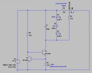
Have a look at this attachment, and the test points. In reality the values will be a little different, but not very much.
It's possible that depending on the LED type, not to show a lot of light with 2-3mA going through.
Iko, that's not for me, right?
That one will run +/-180mA if your Leds can reach 2V Vf for about 2.5mA. Else, about 150mA. R1 sets that. ICCS=(Vf3LEDStot-Vgs)/R1. Fix it given your actual parts. The trimmer gives you an adjustable Vout. Don't ask more than 65V out. You can use BF245A if you can't get 2N5457, don't use anything more than 3mA IDSS collector load, so to keep the error amp BC546B dissipating conservatively. Remote sensing is recommended. You have seen how on the one I showed for Merlin a few pages back. Good luck.
Salas,
Thanks. The R6 configuration, are the trimmer and fixed resistor parallel?
Ken L
Iko, that's not for me, right?
Oh yes, it's totally for you 🙂 You think I took the time to type in all that for nothing? 😀
Oh yes, it's totally for you 🙂 You think I took the time to type in all that for nothing? 😀
Sorry Iko, so if I understand well is possible that LEDs don't shine or shine very low, but the reg. still not works?
Yes. More importantly though, you should measure between 5 and 6 volts across the LEDs.
My advice is to implement the exact schematic (using bc546) that I showed above, and if you measures very close to the values indicated on the schematic, then you have the CCS, a current limiter, working well. Only then move to the next section, the shunt part, without fear. Because no matter what happens in the shunt portion, your current limiter will not allow anything to happen in case of a short circuit in the shunt.
My advice is to implement the exact schematic (using bc546) that I showed above, and if you measures very close to the values indicated on the schematic, then you have the CCS, a current limiter, working well. Only then move to the next section, the shunt part, without fear. Because no matter what happens in the shunt portion, your current limiter will not allow anything to happen in case of a short circuit in the shunt.
Salas,
Thanks. The R6 configuration, are the trimmer and fixed resistor parallel?
Ken L
Like this.
Attachments
- Status
- Not open for further replies.
- Home
- Amplifiers
- Power Supplies
- The simplistic Salas low voltage shunt regulator