If you'd like my help search the schematic, post it here and show the values of any capacitors and resistors that you've changed, then I'll ask you to measure some voltages around the circuit.
R1 / 10ohms, the rest of caps & resistors as the schematic.
Last edited:
An externally hosted image should be here but it was not working when we last tested it.
If needed can I post a picture with the other pcb side?
You mean how you can remote sense any V1.0 I guess. Forget V1.1 when there is 1.2. It was an intermediate step. Here is an example of your 46V V1.0 for Low MC for how to apply sense wiring. That is for just any V1.0 who somebody wants to apply sense wiring. V1.0 is not picking up noise from the sense wiring as easily and it can be done with a twisted pair, same type as the main output force wiring taken from Q4/C4 nodes.
Salas,
Thanks so much for all your work and help to us neophites. Can you post the negative version of this schematic. I've made my negative version and it seems to work in simulation, but, just want to make sure.
Thank
Ken L
If needed can I post a picture with the other pcb side?
Are you using a single heatsink for both mosfets ?
R1 / 10ohms, the rest of caps & resistors as the schematic.
The image is too small, what was the post number please?
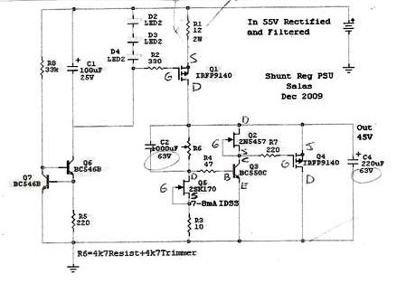
But, if the LEDs are not lit up then the CCS mosfet isn't biased properly. Check the two bjt on the lower left side of the picture. With the DMM on diode test you should read something between B-E and B-C pins, one way only, and the reading should be close in value.
Last edited:
Are you using a single heatsink for both mosfets ?
Yes I am using the old chassis of an Audionote DAC as heatsink for the 4 mosfets.
If they aren't insulated, bingo! Here is your problem. Use your DVM, you must not see zero Ohm between their middle legs. And take out that 150R. Its overloading beyond CCS setting even if when it will work. Find something around 1k to 2k. Or leave it unloaded. I wrote again yesterday.
The image is too small, what was the post number please?
But, if the LEDs are not lit up then the CCS mosfet isn't biased properly. Check the two bjt on the lower left side of the picture. With the DMM on diode test you should read something between B-E and B-C pins, one way only, and the reading should be close in value.
The post number is: 1938
http://www.diyaudio.com/forums/powe...-voltage-shunt-regulator-194.html#post2107103
Salas,
Thanks so much for all your work and help to us neophites. Can you post the negative version of this schematic. I've made my negative version and it seems to work in simulation, but, just want to make sure.
Thank
Ken L
You want the over 40V one capable in symmetric that LaOde uses for D1 and first was used in Italy on EB class A kit amp driver stages?
If they aren't insulated, bingo! Here is your problem. Use your DVM, you must not see zero Ohm between their middle legs. And take out that 150R. Its overloading beyond CCS setting even if when it will work. Find something around 1k to 2k. Or leave it unloaded. I wrote again yesterday.
The mosfets are properly insulated. I used mine DVM & I not see zero Ohm between their middle legs. I only have 1k 5W to load the reg. it's ok?
The image is too small, what was the post number please?
But, if the LEDs are not lit up then the CCS mosfet isn't biased properly. Check the two bjt on the lower left side of the picture. With the DMM on diode test you should read something between B-E and B-C pins, one way only, and the reading should be close in value.
Newbie question: I have to read both BC546B with the power on?
Make sure there is current going through Q6, Q7, R8, and R5. Measure the voltage across R5 for instance, and divide by the value of R5, let us know what it is.
1k 5W is great. Get em out and trace 'em against schematic. Is your trimmer wired like that?
So you want that I replace the 150R 10W for the 1K 5W to load the reg.?
Yes. And I want to be sure that you have the trimmer and its tail resistor Rref system connected as I posted on top of this page.
And I want to be sure that you have the trimmer and its tail resistor Rref system connected as I posted on top of this page.Make sure there is current going through Q6, Q7, R8, and R5. Measure the voltage across R5 for instance, and divide by the value of R5, let us know what it is.
Is necessary that reg. is loaded with 1k 5W before do the measurements?
Make sure there is current going through Q6, Q7, R8, and R5. Measure the voltage across R5 for instance, and divide by the value of R5, let us know what it is.
The voltage across R5 is 0.5V, across R8 is 61.2V
The current is kind of small?
And the LEDs are lit?
What's the voltage across all 3 LEDs? (between Vin and mosfet gate)
And the LEDs are lit?
What's the voltage across all 3 LEDs? (between Vin and mosfet gate)
Yes.
After the mosfet Q1 I have first the resistor & after de trimmer, is necessary to change the order?
- Status
- Not open for further replies.
- Home
- Amplifiers
- Power Supplies
- The simplistic Salas low voltage shunt regulator