Yes, cap stays. It will go 50% dissipation of a 1/4W. After you tune the value (I gave you rough approximation, can't be a bullseye without measuring there), and if all is well, you can find 1W and replace for long term.
I wonder how using a resistor instead of a zener will effect output Z? Maybe the Z of the reference will be swamped by the large cap?
Maybe Iko can sub it in his V1 sim and let us know. Me I have tried several times in practice for changing some Vout fast, and its very decent in noise mainly.
Paralleling a trimmer across the R might also be a nice way to set the Vout accurately & give a limited range of Vout adjustment i.e 12V to 19V. Might require a change of Vin also?
It will stress the ccs dissipation if in heavy shunt when going low and having Tx for high. In a light current shunt, cool. Gives an adjustable one. Have said to jameshill in an old post again. Maybe with 2 seconadries and a switch for them & resistors?
Can't sim now, but I wouldn't worry about zout with resistor replacing the zener. Just leave the cap across the resistor.
Edit: sim agrees, you're fine with a resistor.
Edit: sim agrees, you're fine with a resistor.
Last edited:
Iko,
Thanks for bringing me here.
Salas, Iko and guys,
I am happy to build both Salas v1 and Iko v2. I think I will approach it this way - I will start building the Salas v1 as soon as I have my questions sorted out and parts ordered. This is to drive a single OPA627 buffer, nothing else, on +/-15VDC rails. For v2, from what I have read, only Iko and Pham have built it. It is probably beyond my ability and skills to do it. But still, I am happy to give it a try, to be a "tester" for v2. Before I complete v1, v2 will progess in the background for preparation only. Once good sonic is realised in v1, v2 will follow. The purpose of v2 is different, and it will drive 22 opamps on +/-15VDC rails.
Could you please kindly supply the schematics / parts for both the + and - 15VDC rails for a single OPA627 buffer? Actually the rails can be anything from +/-12VDC to +/-15VDC.
I am a novice so thanks in advance for your patience.
Regards,
Bill
Last edited:
Welcome to the thread Bill! I tell you, with salas, it's always been a fun ride for me 😀
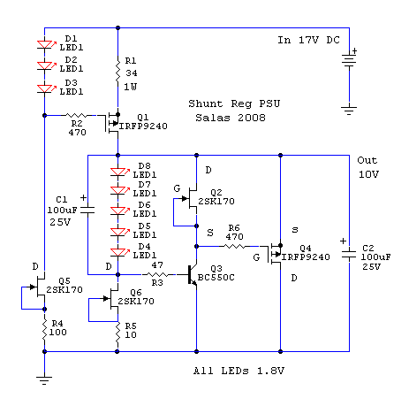
OK, let's get down to business. Have a look at this, it comes with a nice layout too, due to one very talented member here.
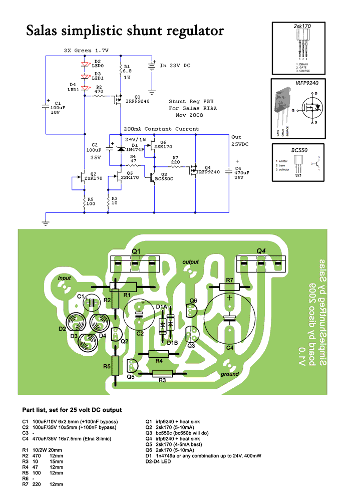
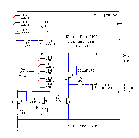
R1 sets the current limit (total current passed). The total current will be roughly made up of the current drawn by the load, plus the current through the shunt mosfet (I'm just ignoring the vref current now). You can set the desired voltage output with an appropriate choice of zener diode. Input voltage should be about 10V above the target voltage. There's a negative version of this circuit too, but I don't have it handy, maybe when salas wakes up 😀 (he never sleeps really).
OK, let's get down to business. Have a look at this, it comes with a nice layout too, due to one very talented member here.
R1 sets the current limit (total current passed). The total current will be roughly made up of the current drawn by the load, plus the current through the shunt mosfet (I'm just ignoring the vref current now). You can set the desired voltage output with an appropriate choice of zener diode. Input voltage should be about 10V above the target voltage. There's a negative version of this circuit too, but I don't have it handy, maybe when salas wakes up 😀 (he never sleeps really).
Thanks, Iko. I am totally unfamiliar with parts. Which zener to use to give 15V?
With the JSR, I like the sound without the bypass capacitor around the zener, I wonder if that applies here too?
C4 is a Elna Silmic. I had 2 dozens of them on my Marantz SA11 (made in Japan, around US$3,000?) but I didn't like their sound and removed and sold them. They are warm, tube-like sounding but coloured in my personal opinion. I don't like the sound of electrolytic capacitors, but if I have to have them, I prefer Rubyzon ZL, much cleaner, neutral sounding, and faster but with a peaky treble. It is quite low in impedance so I wonder if it works here.
As for heatsinks, I prefer to be on the safe side and don't mind over doing it, i.e. the CSS must not overheat on full load, and the shunt must not overheat on no load.
OK. I have had a headache since this morning and have to retire to sleep. I will get back to this tonight (Sydney time).
And am anxiously awaiting for the schematic for the negative supply.
Regards,
Bill
Sorry to hear about your headache.
The zener can be a 1N4744A. I would not remove that cap. V1 has been extensively tested and tweaked by people with good ears, and the consensus is that the cap is needed. My noise measurements confirm this. But best is to make your own mind.
About the choice of caps, salas and nicoch46 can say much more. The thread in which salas has first made the regulator available is this
http://www.diyaudio.com/forums/showthread.php?t=129126&page=242
There are many comments there about tweaks, but it's also a long thread. 🙂
About heat sinks. The inherent workings of the shunt are such that the more current the load draws, the less current will go through the shunt mosfet (the mosfet that passes current to ground). The CCS mosfet, the one after R1, passes a steady total current all the time. The IRFP9240 and IRFP240 are TO-247 devices, they can dissipate quite a lot of heat if properly heat sink-ed.
Have a look at these two.
Edit: this is V1
Last edited:
Hi Salas, Ikoflexer and everyone,
I need a schematic of Salas V1 for my DAC which require +15V at 68ma and -15V at 43ma.
I have a two dual 15V transformer already.
I would be gratefull if you have any equivalent schematics for me.
I have a question for the voltage reference, for example because I need 15V output if I place a 9V zener in serie with three 1.8V led would this be OK?
Thank you
ncc
Yes, LEDs in series with the zener shouldn't be a problem. For schematic, see my post before yours (post 1191). That is V1.
Hi Salas, Ikoflexer and everyone,
I need a schematic of Salas V1 for my DAC which require +15V at 68ma and -15V at 43ma.
I have a two dual 15V transformer already.
I would be gratefull if you have any equivalent schematics for me.
I have a question for the voltage reference, for example because I need 15V output if I place a 9V zener in serie with three 1.8V led would this be OK?
Thank you
ncc
Don't use a 9V zener, its one of the bad noise zener region. Use 7 - 8 red leds instead. Match them and see how near 15V they get you. Polarity of leds is the same as the 3 leds go in above schematics in each positive and negative shunt. R1=15R 2W is enough current for your application, +/- 150mA CCS. 6R8 runs it above 200mA with most leds. Not necessary.
Thank Salas and Ikoflexer !!!
to day I finish the Salas shunt for my DAC!
I think It is very good, and wonderfull, I draw again cricuit, anh I make some
board!
I use tow LEDS and Trim change to zener! That is better!
thank you again!
QuangHao
to day I finish the Salas shunt for my DAC!
I think It is very good, and wonderfull, I draw again cricuit, anh I make some
board!
I use tow LEDS and Trim change to zener! That is better!
thank you again!
QuangHao
Attachments
I forgot to mention, everyone. For the easy entry to V1, have a look at this:
http://www.diyaudio.com/forums/showthread.php?p=1941578
There's a group buy for a nice board which includes dual rail regulator, direct coupled B1 buffer, and soft start. But some people get the boards only for the regulator (easy to change voltage out, current, etc.).
Disclaimer: I have nothing to do with the GB, just mentioned it in case it may be helpful.
GB
http://www.diyaudio.com/forums/showthread.php?p=1941600#post1941600
salas, you weren't around earlier so I took the liberty to post a dual rail schematic of V1. Let me know if I should change anything. 🙂
Thank Salas and Ikoflexer !!!
to day I finish the Salas shunt for my DAC!
I think It is very good, and wonderfull, I draw again cricuit, anh I make some
board!
I use tow LEDS and Trim change to zener! That is better!
thank you again!
QuangHao
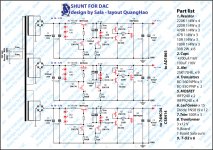
Great draw quality schematic. Thanks. Seems I got a new nickname in the Far East.😀
All the guys who want a DAC 5V version may refer to this. Endorsed for visual clarity and optimum Vref. The 100R in series with two leds is a trimmer.
The resistor in the CCS IRFP9240 is the 470R.
I forgot to mention, everyone. For the easy entry to V1, have a look at this:
http://www.diyaudio.com/forums/showthread.php?p=1941578
There's a group buy for a nice board which includes dual rail regulator, direct coupled B1 buffer, and soft start. But some people get the boards only for the regulator (easy to change voltage out, current, etc.).
Disclaimer: I have nothing to do with the GB, just mentioned it in case it may be helpful.
GB
http://www.diyaudio.com/forums/showthread.php?p=1941600#post1941600
salas, you weren't around earlier so I took the liberty to post a dual rail schematic of V1. Let me know if I should change anything. 🙂
http://www.diyaudio.com/forums/showthread.php?p=1941578
There's a group buy for a nice board which includes dual rail regulator, direct coupled B1 buffer, and soft start. But some people get the boards only for the regulator (easy to change voltage out, current, etc.).
Disclaimer: I have nothing to do with the GB, just mentioned it in case it may be helpful.
GB
http://www.diyaudio.com/forums/showthread.php?p=1941600#post1941600
salas, you weren't around earlier so I took the liberty to post a dual rail schematic of V1. Let me know if I should change anything. 🙂
I have seen it before I went voting. Its OK.
I may remind that the DCB1S shunt's part is tuned to it, and I would prefer jameshill pcb liberty. I run the positive Vref harder on that GB's shunt part for special reasons.
Thanks Iko for keeping the thread informative.
I may remind that the DCB1S shunt's part is tuned to it, and I would prefer jameshill pcb liberty. I run the positive Vref harder on that GB's shunt part for special reasons.
Thanks Iko for keeping the thread informative.
Cool. Yes, James did a very nice job on the layout. Here's the link to his work:
http://www.diyaudio.com/forums/showpost.php?p=1834221&postcount=226
At some point it'd be nice to start a wiki with all the different layouts, etc.
Voting eh? It seems your taxes will go up 😀 the left is winning?
http://www.diyaudio.com/forums/showpost.php?p=1834221&postcount=226
At some point it'd be nice to start a wiki with all the different layouts, etc.
Voting eh? It seems your taxes will go up 😀 the left is winning?
- Status
- Not open for further replies.
- Home
- Amplifiers
- Power Supplies
- The simplistic Salas low voltage shunt regulator