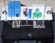
Marinos said:I use teflon for years now. Very easy to work with. I use those standard brown predrilled boards that you use to make the layout. I mark the holes with a pencil, attach the teflon sheet underneath and drill. The photo shows a guide for 4 shunts board 😉
Nice way to do it. P2P & Teflon, purest way I guess. I have seen it on your high voltage supply too. Thanks.
Attachments
Iko, why Marinos reports such a big difference for the better subjectively when shunt powering OPA627s, which are high PSRR circuits? He already had batteries for years. I see he has long enough cabling from the shunts to the circuit. Yet his sound boomed. Is it beyond psrr and output impedance? My guess is that the simple shunts put minimal components between audio and power, and have only local loops. Must be a major factor for the tone.
Are teflon boards easy to find where you are?
There is hardware store at Athens center that I always find it and it is cheap. I suppose that it is not widely available..
I must come back to Athens not only to visit the new museum then... 😀
P.S. Elgin marbles must come back to Greece!
P.S. Elgin marbles must come back to Greece!
which one popped?ikoflexer said:it happened usually very fast. I'd hear a pop and done
M1, M2 or M4?
Salas said:Iko, why Marinos reports such a big difference for the better subjectively when shunt powering OPA627s, which are high PSRR circuits? He already had batteries for years. I see he has long enough cabling from the shunts to the circuit. Yet his sound boomed. Is it beyond psrr and output impedance? My guess is that the simple shunts put minimal components between audio and power, and have only local loops. Must be a major factor for the tone.
Interesting. I've recently come across a rave review by Lynn Olson on the LNPA-150 amp. Apparently the amp was all solid state, no boutique parts, no extraordinary topology, yet it sounded extraordinary. The amp had a discrete regulator. He theorizes in some other places about the regulator somehow isolating the amp from the bank of capacitors which he thinks is in part responsible for the bad sound of most SS amps.
My experience with batteries was "sluggish" sound and as soon as I used your regulator the dynamic acquired was great. There is something to be said about a low noise circuit, and that gives current fast and when it's needed, in the same time keeping the voltage more constant.
These are some of the reasons why I'd like to get my tube (power) headphone amp regulated asap.
AndrewT said:which one popped?
M1, M2 or M4?
Andrew, it was this schematic that I was using at the time.
But instead of the irf840 I used irfpc60 and some other n-channel high voltage high power mosfets. It was the shunt mosfet (irfpc60) that usually got burned. Now I recall that it would often oscillate as well. It was probably just badly built by me.
c2 will hold the ref voltage down while it starts to charge.
The shunt will try to keep the output voltage down to match the ref voltage and as a result dissipate the full CCS current at the full input voltage until it overheats.
The shunt will try to keep the output voltage down to match the ref voltage and as a result dissipate the full CCS current at the full input voltage until it overheats.
massimo said:I must come back to Athens not only to visit the new museum then... 😀
P.S. Elgin marbles must come back to Greece!
Today is the opening and you can watch it live from this link Acropolis museum
Scenes I have seen from television sent chills to my body.. The way that the objects has been placed in space gives you a spooky feeling that statues are visitors themselves ... Something that must be seen.
Follow the link and you will understand/feel why the "elgin marbles " are not just marbles and must come back and "fill the holes in their family photo"
Marinos said:
Follow the link and you will understand/feel why the "elgin marbles " are not just marbles and must come back and "fill the holes in their family photo"
Thank you for the link.
I'm sorry for Andrew who's Scottish as well, but I consider what mr Elgin did two centuries ago a robbery. And only to decorate his private house!
They must be returned to you as Italy did with some parts of famous Greek statues or Axum stelae stolen last century and recently returned to Ethiopia. For once we did it right!
Hi all,
As some have found, the 2SK170 is not widespread in its availability.
I can get the dual version 2SK389 here, but was thinking of the 2SK246 (GR or BL class). Will this work OK? I just wanted to buy locally if possible.
http://www.toshiba.com/taec/components2/Datasheet_Sync//53/6917.pdf
Cheers
Stuey
The one under the Zener must work under BC550's Vbe. Thus its Vgs (off) must be under 0.7V. 2SK246 gives 0.7V as minimal. A solution would be to lift the Vbe to about 2.5V by using a 220R under BC550, emitter to ground. Assuming an Iccs load on its collector of about 8.5mA IDSS.
HV OT.
The shunt Mosfet dissipates less power the less the voltage across it, given the standard CCS current minus what goes to load consumption during start up as C2 charges. In a strong set current scenario, I would be more concerned about the CCS Mosfet which will have to endure more Voltage than final Vin-Vout and full current. The shunt Mosfet pops by oscillation IMO. I would remove C2, see if it does better, and then use a 0.22uF one or 0.33uF to see if it still holds. There is enough Johnson on a 82k we would not want to amplify, left totally unfiltered. Non the less all the working shunts made by now, do have C2 and don't pop. One thing we know is that no working example has been made beyond 100-120mA. Also he must play better safe than sorry and use safety Zeners across Mosfets. I don't use any bcs of no problems, and I avoid their self noise. But Iko suffered problems and must take precautions. Another thing that crosses my mind is what if the Zobel values are not good with the alternative than IRF840 Mosfets Iko uses, and what about any reaction from his amplifier used as load. As for things particular to Iko's test build, as possible culprits or not, naturally we can't know more.
HV OT.
AndrewT said:c2 will hold the ref voltage down while it starts to charge.
The shunt will try to keep the output voltage down to match the ref voltage and as a result dissipate the full CCS current at the full input voltage until it overheats.
The shunt Mosfet dissipates less power the less the voltage across it, given the standard CCS current minus what goes to load consumption during start up as C2 charges. In a strong set current scenario, I would be more concerned about the CCS Mosfet which will have to endure more Voltage than final Vin-Vout and full current. The shunt Mosfet pops by oscillation IMO. I would remove C2, see if it does better, and then use a 0.22uF one or 0.33uF to see if it still holds. There is enough Johnson on a 82k we would not want to amplify, left totally unfiltered. Non the less all the working shunts made by now, do have C2 and don't pop. One thing we know is that no working example has been made beyond 100-120mA. Also he must play better safe than sorry and use safety Zeners across Mosfets. I don't use any bcs of no problems, and I avoid their self noise. But Iko suffered problems and must take precautions. Another thing that crosses my mind is what if the Zobel values are not good with the alternative than IRF840 Mosfets Iko uses, and what about any reaction from his amplifier used as load. As for things particular to Iko's test build, as possible culprits or not, naturally we can't know more.
HV OT.
oops
During start up, the low voltage across C2 forces the CCS to dissipate more power.
Salas, you're right.Salas said:The shunt Mosfet dissipates less power the less the voltage across it, given the standard CCS current minus what goes to load consumption during start up as C2 charges.
During start up, the low voltage across C2 forces the CCS to dissipate more power.
Salas said:The one under the Zener must work under BC550's Vbe. Thus its Vgs (off) must be under 0.7V. 2SK246 gives 0.7V as minimal. A solution would be to lift the Vbe to about 2.5V by using a 220R under BC550, emitter to ground. Assuming an Iccs load on its collector of about 8.5mA IDSS.
Thanks Salas.
Built one based on Iko's post #456 and hooked up to a Monica 3 DAC for burning in now. It works fine and the noise floor is at least as low as v1 that I built earlier.
Tham said:Built one based on Iko's post #456 and hooked up to a Monica 3 DAC for burning in now. It works fine and the noise floor is at least as low as v1 that I built earlier.
That's cool! Any details on the parts used, sound tone change, etc.? BTW, I felt the other day like pushing the limit a bit, and used two mpsa18 instead of mpsa20, and darlingtoned the bd140 with a 2sa564 in front of it. Didn't use any compensation caps, and it was stable on some brutal loads. I measured half the ripple on sine wave load. Just something to keep in mind.
- Status
- Not open for further replies.
- Home
- Amplifiers
- Power Supplies
- The simplistic Salas low voltage shunt regulator