After so many made and at work for over 6 months now, with all builders happy, from 90mA to 3A, I guess we just need a fine PCB artwork basically. With good nodes, earthing, and a mirror negative with IRF240s. Jwb's is very good, but it is integrated application specific at low mA, with no sinks provision and uses TO-220 9610s...
Salas said:After so many made and at work for over 6 months now, with all builders happy, from 90mA to 3A, I guess we just need a fine PCB artwork basically. With good nodes, earthing, and a mirror negative with IRF240s. Jwb's is very good, but it is integrated application specific at low mA, with no sinks provision and 9610s...
Agree 100%. I hope James didn't give up on the pcb layout.
He said he is up to the neck with projects though and he did not touch it at all yet.🙁 (You probably mean Kent from the Riaa thread, yes?)
Lumba Ogir said:No noise regulator...
Lumba, there are a few things that are sort of off in your schematic. C1 has an effect when connected past the resistor, not before. In essence it bypasses both the bjt and the resistor at high frequencies. Also, higher current on the mosfets gate will help against their input capacitance. You may try some simulations and see for yourself.
salas, I don't know, Kent seems to have disappeared. That'd be sad, as his artwork was outstanding.
Edit: yes, I meant James. I'd do the layout myself but you've seen the one I posted in the riaa thread, it had the finesse of an axe sculpture. Beautiful drawings are not my thing.
The first basic "Salas one" is finished (as per post #198), and ready for your perusal - I'll send it off to you tonight - It's looking rather promising, if I say so myself!
Then onto this tl431 idea and those other options later and expand the board a bit and see how it all comes together.
Iko, I'll see about your extra "string variation" after that.
Lumba, I see that your cct has the cap C1 is connected between the R4 and T2 rather than R4 - T3, as in Salas' one - is there a particular reason for this difference?
I saw that Martin, on the Toole reg thread, has opted for the same type of CCS as yours, Salas, and now it just has the extra gain stage on the shunt control and uses transistors rather than Fets.
Later .....
As an ongoing slightly separate thread, I have been trying to widen the output impedance bandwidth with no ill effects on the other desired parameters. This is the topology I am converging to, not yet refined. More tests need to be done, of course.
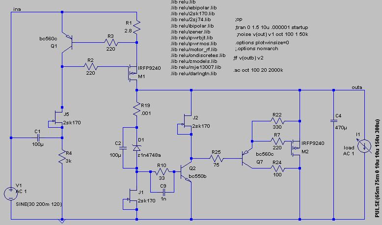
The output impedance.
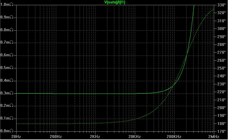
This version does not need to run a large current through the shunt mosfet to achieve the low output impedance, which is good. It also seems stable.
Comments/suggestions appreciated.
The output impedance.
This version does not need to run a large current through the shunt mosfet to achieve the low output impedance, which is good. It also seems stable.
Comments/suggestions appreciated.
jwb said:Nice result ... but is it stable?
I usually do my best to make it unstable in simulation, before building it for real. Saves time, of course. So, I've been putting this circuit through quite a few tests and it is stable in simulation. Do not pay too much attention to the exact size and configuration of resistors around the mosfet, those are not refined yet and will change. The topology though, seems promising, and this was what I was looking for. We'll see if it lives up to its promises.
We are discussing a nice PCB for the original shunt with James. We will show soon. If you end up with a nice and practically tested upgrade, that will be V2. I am a bit suspicious that cabling resistance and inductance can easily swamp things though. Please check if you can spot audible upgrade too on headphones when you make V2. If surely ''yes'' I am sure that nobody will see the added components as a turn off.
Good luck Iko! Thanks.🙂
Good luck Iko! Thanks.🙂
Salas, I agree that trace or wire inductance can obviate improvements in output impedance (or induce phase shift leading to instability). That's why I recommend integrating the regulator right on the board with the load, instead of trying to build a regulator on a daughterboard connected with wires and terminals.
A reasonable compromise is to build the regulator on a daughterboard, but attach it directly to the load with soldered pins.
A reasonable compromise is to build the regulator on a daughterboard, but attach it directly to the load with soldered pins.
I know, that is really the best...alas this is a general purpose regulator here. But I highly recommend your way for planned integrated builds.
Did you finish it? Have pics?
Did you finish it? Have pics?
Yes, good points guys, thanks! I've started, as a habit now, for every new variation to run a battery of tests that try to address several issues that may plague a regulator. Regarding trace resistance and inductance, I add small inductors (which have series resistance too) to the circuit at various places in the circuit and then run various simulations and observe the effect. Many of the results I don't write here about because of lack of time. I also think I should spare most people the boring stuff.
Now, a few particular comments. Both the original circuit and the experimental V2 are very sensitive to trace resistance and inductance. Both circuits can be stabilized with and extra one or two capacitors. Both circuits suffer equally (proportionally) as far as output impedance goes from trace parasitics. The moral of the story here is, pcb layout is crucial to get in real life performance that has any semblance to simulation. I've said it before, but allow me to repeat. The traces around the shunt mosfet are paramount to get right. It's probably best to use smd parts as much as possible there. Trace parasitics in that area show large detrimental effects in simulation. I can only imagine how bad it is in real life.
I will start building a prototype v2 when I'm reasonably satisfied with the simulated tests, and will report.
Edit: typos.
Yes, Ikoflexer good work.
There is a lot to be learned from Salas's design...............but the way it is going this thread will have to be renamed The super complex Salas low voltage regulator.😀
Let's hope it does not start to resemble the regulator below 😉 ............ with all due respect to Chokey.
Regards,
Jam
There is a lot to be learned from Salas's design...............but the way it is going this thread will have to be renamed The super complex Salas low voltage regulator.😀
Let's hope it does not start to resemble the regulator below 😉 ............ with all due respect to Chokey.
Regards,
Jam
Attachments
Thanks for the encouragement! 
He, he... the lure of "Christmas tree" design. It can happen to the best of us. 😀
Seriously now, I too like simple, and good, and robust, and easy to do. That's what attracted me to salas' design in the first place. We already have v1 which is very simple and everybody can and should build that. The super-complex v2 is only for the daring soul 😀
Is this a trick question? BTW, it's very easy to run this sort of thing, you should try it, ltspice is free.
Edit; I realize you're probably running ltspice already. I guess I don't know which test to run on this circuit. What would you like to find out about it?
Edit; I realize you're probably running ltspice already. I guess I don't know which test to run on this circuit. What would you like to find out about it?
Attachments

- Status
- Not open for further replies.
- Home
- Amplifiers
- Power Supplies
- The simplistic Salas low voltage shunt regulator