Dear friends,
I'm not sure if there are several versions of the Salas low voltage reg, a lot of posts, which I couldn't read completely. Can anybody help me to get the newest design?
Many thanks,
Stammheim
I'm not sure if there are several versions of the Salas low voltage reg, a lot of posts, which I couldn't read completely. Can anybody help me to get the newest design?
Many thanks,
Stammheim
I'd really like to purchase one of these boards but it does not appear to offer a negative supply soluton. Does anyone know of a good shunt reg for negative voltages?
Bib (sslv1.1) pcb is three breakable sections (positive negative positive). 1.2R has a negative schematic too. The designs are fully published and discussed to bits, you can even home etch your own.
Sadly what I really need is a regulator that can go down to at least -300v. I guess I'll just have to build one.
Probably 600ma maximum since I'll be playing with higher current tubes soon. I'm trying to find a convenient all-in-one power supply solution for prototyping.
Well then I guess you have to turn to the soldering iron for that. Not even the biggest aftermarket HV LAB PSUs specs that.
Hi Salas,
I'm not sure if this question had been asked before.
Can the Reflektor configure for 12V output?
Thanks
Ken
I'm not sure if this question had been asked before.
Can the Reflektor configure for 12V output?
Thanks
Ken
Yes especially when sinked on bigger external surface unless the constant current setting is low and on board sinks can still cope. Vref LM329 as super quality zener + Leds should do the 12V trick.
Moved here from another thread...
I have it now. Where I went off-track was thinking I needed an opposite for the BF256. But I don't need a p-chan, just flip the n-chan. Exactly as drawn in the schematics. Jeez, when will these people learn to read?
Thank you for your patience!
The V1.2R regs with cascoded JFET CCS "tail" we discussed JFET equivalents for are positive and negative designs already that use NJFETs only. For MOSFETS and BJTs they use opposites. They are the first two schematics from the "revision" link in post #2 of the "The simplistic Salas low voltage shunt regulator" thread. The thread where this discussion belongs better by the way.
I have it now. Where I went off-track was thinking I needed an opposite for the BF256. But I don't need a p-chan, just flip the n-chan. Exactly as drawn in the schematics. Jeez, when will these people learn to read?
Thank you for your patience!
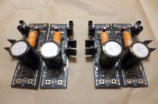
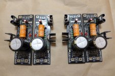
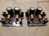
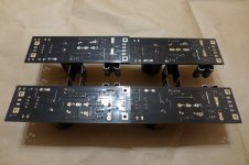
I'd like to share my current BLB 1.1 builds. They're dedicated for the analog power supply of my future high-end DAC project with PCM56.
The regs are tuned to ~100mA at and are built with the following:
-Boards from TeaBag (many thanks for the group buy).
-Epcos (Siemens) Sikorel 680uF as Vref
-Nichicon Gold tune 8200uF as first filter capacitor
-BYV26C rectifier diodes.
-Siemens MF 10R CCS resistor.
-Elna Cerafine 22uF final filtering capacitor
-Draloric, Philips and Resista MF resistors for the rest of the circuit board
-The CCS and the shunt power transistors are from TeaBag's kit materials.
-The sk117, sk184 and BJTs are bought from a local shop.
Photos:


Best regards,
Alexander.
The regs are tuned to ~100mA at and are built with the following:
-Boards from TeaBag (many thanks for the group buy).
-Epcos (Siemens) Sikorel 680uF as Vref
-Nichicon Gold tune 8200uF as first filter capacitor
-BYV26C rectifier diodes.
-Siemens MF 10R CCS resistor.
-Elna Cerafine 22uF final filtering capacitor
-Draloric, Philips and Resista MF resistors for the rest of the circuit board
-The CCS and the shunt power transistors are from TeaBag's kit materials.
-The sk117, sk184 and BJTs are bought from a local shop.
Photos:
Best regards,
Alexander.
Attachments
Nice photos and carefully selected parts. Wishing you good luck for the final DAC build Alexander.
Thank you Salas. One of the upgrades for the project will be the LC filtering of the power supply before the regulator. I'm a big admirer of choke input filtering because of their technical and most of all sonic advantages. I haven't wound the chokes yet, so at first the project will be powered with the default capacitor input filtering. My power transformers have a secondary tap on the secondary tap for a higher voltage, which will compensate for the choke input filtering supposed voltage drop.
Of course I do not intent to barbarically split the trace before the capacitor. The solution will be moving the rectifier outside the board, together with the choke.
Regards,
Alexander.
Of course I do not intent to barbarically split the trace before the capacitor. The solution will be moving the rectifier outside the board, together with the choke.
Regards,
Alexander.
Measure twice, cut once
To be sure... v1.2R... negative regulator... Q7 collector to Q8 drain... right?
To be sure... v1.2R... negative regulator... Q7 collector to Q8 drain... right?
There are several ways. For example two greens and a diode instead of R103, everything else jumpered. Or two red and 500R trimmer, everything else jumpered.
Thank you Salas. One of the upgrades for the project will be the LC filtering of the power supply before the regulator. I'm a big admirer of choke input filtering because of their technical and most of all sonic advantages.
Alexander.
Why go half-baked. Why not a PI filter?!
- Status
- Not open for further replies.
- Home
- Amplifiers
- Power Supplies
- The simplistic Salas low voltage shunt regulator