Mild periodic oscillations are difficult to detect without a scope (it better be a reasonably fast model so to can see even small crests of weirdness). But systematic oscillation usually gives clues by side effects like overheating, buzz, unsettling bias current, hard sonics.One thing i forgot to say concerning my previous post:
When i say that it works fine, it means it is showing the desired voltage on my multimeter.
i have no oscilloscope to confirms it is working as intended. All my impressions are therefore subjective.
Mild periodic oscillations are difficult to detect without a scope (it better be a reasonably fast model so to can see even small crests of weirdness). But systematic oscillation usually gives clues by side effects like overheating, buzz, unsettling bias current, hard sonics.
thanks...noted!
Regarding irf610 and depletion MOSFETs....i tried already the irf610 as cascode, but found nothing to write home about. However, i like them in the CCS with a string of leds instead of bjt.
...but i may just retry to be certain...😀
i thought about testing a depletion device... Maybe (probably) sometimes in the future. I like how they reject voltage at the drain pin, but i'm afraid that they might be a bit noisy.
Whatever you like best. But save for a scope, it will help you a lot since you delve into circuitry blocks. I would recommend this rather affordable one https://www.youtube.com/watch?v=r9mQBti0b8o
Whatever you like best.[/url]
1) i'm not saying irf610 cascode was bad. it just didn't strike me as having a caracther of it's own...maybe i'm just trying to convince myself after all 😀...i think i will try again in my circuit at test.
2) Thank for the link! I'm contemplating since a few years about buying one, but i begin to find this hobby very time consuming 😛
3) small question: what reduces most the chances of oscillation when paralleling like i do? Should just everything be as close as possible or some particular traces matter more? What about a solid ground plane.... can it help?
(i have begin etching my own PCB recently (vinegar,peroxide,cutex, 😀) so with a double sided copper clad, i can do a "ground plane")
Last edited:
Very near, gate/base stopper resistors. Ground plane is good for avoiding loops and helps shielding.
another note on using small signal bjt cascode ccs, just in case one would be tempted to build one:
Paralleling bjt's is not as simple as slapping some togheter randomly, i realized. i went into thermal runaway with my setup.
i made the following discoveries:
-thermal coupling and keeping the temperature down helps balancing, more than close electrical matching of devices
-higher hfe selection leads to more instability.
having said that, i'm running right now 3 bc546b, free standing, in parallel with around 240mW and 1 Ohm degeneration on each, and it is stable. Vbe and hfe are matched but not particularely closely
Emitter ballasting will be determined primarily by the degree of Vbe mismatch among devices. A tenth of a volt across the given resistor should be enough for about the worst-case mismatch.
If the circuit as well requires fairly large impedances in the bases, then you do need to worry about hfe matching to some extent.
I've seen people get into trouble with the standard "Vbe multiplier" when done with a single transistor, when the voltage divider to the base is a too-high resistance. One is counting on the ~ -2.2mV/C Vbe tempco (for an NPN), but the beta has about a +0.5%/C tempco for small and medium current densities. So this countervailing effect is fighting the desired tempco. An integrated Darlington is a good choice, provided you want at least compensation for two Vbe.
Bcarso,
-yes it is better to match Vbe and Hfe. However all the Vbe i measured for my small signal devices were well within 1%. In that case better match the emitter resistors also i guess...
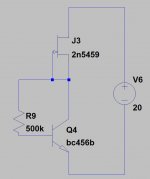
-i used the attached schematic for matching (looking for same Vce devices)
-Wouldn't higher emitter resistors kill gfs?
-for the rest of your post, i'm still digesting...
-yes it is better to match Vbe and Hfe. However all the Vbe i measured for my small signal devices were well within 1%. In that case better match the emitter resistors also i guess...
-i used the attached schematic for matching (looking for same Vce devices)
-Wouldn't higher emitter resistors kill gfs?
-for the rest of your post, i'm still digesting...
Attachments
Last edited:
I had a headphone amp and I built a couple of salas reflecktor 15V to power it.
But do I need to remove two 100u 25V rail decouple capacitor on my PCB to use it with salas PSU?
But do I need to remove two 100u 25V rail decouple capacitor on my PCB to use it with salas PSU?
I had a headphone amp and I built a couple of salas reflecktor 15V to power it.
But do I need to remove two 100u 25V rail decouple capacitor on my PCB to use it with salas PSU?
located before or after the reg?
normally, the regulator likes to see a "specific" capacitance at it's output
schematic/diagram would help.
Reflektor has it's own thread also...maybe you'll find something over there.
sorting for hfe
The tricky thing about sorting for hfe is parsing out the Early effect, the non-zero conductance at the collector. So to begin with the collector should be at a fixed potential relative to the base, ideally representative of the application intended. For minimal thermal distortion and a mostly-constant voltage with variable current, the lower the quiescent dissipation the better.
There are other (generally second-order) mechanisms that lead to errors from the use of an overly simplified model. Subthreshold breakdowns among them.
Of course matching is just that, so unless a test fixture is hopelessly unstable, it can be useful even if not metrological.
I had a headphone amp and I built a couple of salas reflecktor 15V to power it.
But do I need to remove two 100u 25V rail decouple capacitor on my PCB to use it with salas PSU?
You don't have to but you may test without them. If still remaining a stable system it will also be free of their characteristics as Reflektor is designed to can do OK on its own Zobel termination. But those capacitors could have been designed as indispensable local decoupling to the client circuit so it takes to test with and without them to find out.
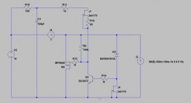
Am i running into possible problems if i do this mod for 3.3v output...?
motivation is that from experience (and a bit of speculation 🙂), the jfet supplying the reference bjt benefits from having "breathing space".
note: please don't mind the parts used. I only show the schematic for topology...
motivation is that from experience (and a bit of speculation 🙂), the jfet supplying the reference bjt benefits from having "breathing space".
note: please don't mind the parts used. I only show the schematic for topology...
Attachments
Increased the voltage to 24VDC at input and the output being at 13.2V and now with a variation of +/-5V the CSS is stable.As Andrew said already you need to exceed the recommended minimum Vin-Vout first so the CCS will stabilize. After that point there will be controlled voltage drop differences across the setting resistor possible values due to the Vgs curve vs Id as seen in any particular MOSFET's manual and little ones due to VDS and rising thermals. In your example the first input voltage is insufficient, that is why you see a marked difference when applying that second still short but more appropriate input voltage.
I have a question that how to get 3.3V output from the bib?
You don't have to but you may test without them. If still remaining a stable system it will also be free of their characteristics as Reflektor is designed to can do OK on its own Zobel termination. But those capacitors could have been designed as indispensable local decoupling to the client circuit so it takes to test with and without them to find out.
Thanks for your answer. I will test and will find out which way will be the best!
Increased the voltage to 24VDC at input and the output being at 13.2V and now with a variation of +/-5V the CSS is stable.
I have a question that how to get 3.3V output from the bib?
Only by making the BJT output Bib version. Its in the manual. But I don't recommend it for 3.3V bcs its marginal.
The tricky thing about sorting for hfe is parsing out the Early effect, the non-zero conductance at the collector. So to begin with the collector should be at a fixed potential relative to the base, ideally representative of the application intended. For minimal thermal distortion and a mostly-constant voltage with variable current, the lower the quiescent dissipation the better.
There are other (generally second-order) mechanisms that lead to errors from the use of an overly simplified model. Subthreshold breakdowns among them.
Of course matching is just that, so unless a test fixture is hopelessly unstable, it can be useful even if not metrological.
thanks for the the explanation!
I will have to digest a bit...
concerning my "bjt tester", what i can say for now is i choose the resistor value to give me around 10 volts Vce, to be sure to be in the active region.
I will have to test a few more bjt's with a bit more care to see if it can be of any utility and get relatively close match, because the current share reading i have is inconcluding. Also, as you said, maybe 1 ohm emitter resistor is a bit low for around 15 mA collector current.
note: the bjts i "matched" are around 10, 10 and 16 mA.....and then i added randomly two more that settled at 17 mA and 8mA.....for a total of around 60mA.
Last edited:
im trying to incorporate this circuit into the regulator because i like what it does to the sound.
where do you recommend i put it for the gyrator to dominate the sound?
as of now i'm trying to etch it right on the output before the last filtering cap.
where do you recommend i put it for the gyrator to dominate the sound?
as of now i'm trying to etch it right on the output before the last filtering cap.
Last edited by a moderator:
Incorporate as pre-reg filter. But make sure to check with an oscilloscope that it will not interact for oscillations or weird noises with the regulator's input. Contstant voltage circuit for the output of a reg rather not. Just pasted in a complete regulator especially without full analysis could even bring disaster. CVS (gyrator) is sometimes found as anode load in tube circuits.
- Status
- Not open for further replies.
- Home
- Amplifiers
- Power Supplies
- The simplistic Salas low voltage shunt regulator