Final decision.... 1000uF MUSE bypassed by a 47u BG.
Wonderfull stuff 🙂
Big bass with a hint of BG magic in the highs.... No need for more.
Wonderfull stuff 🙂
Big bass with a hint of BG magic in the highs.... No need for more.
hehe... just joking.
But 1000u seems to be the minimum to obtain a good Bass / Trebble equilibrium.
And it does not loose any highs even if you use a larger cap like 2200u. Very good.
Tomorrow the gate stoppers 🙂
But 1000u seems to be the minimum to obtain a good Bass / Trebble equilibrium.
And it does not loose any highs even if you use a larger cap like 2200u. Very good.
Tomorrow the gate stoppers 🙂
I don't know from schematics and layouts that I did not personally issue. There could be corrections later on, whatever. Copy from my posts in this thread, and invest on a scope as soon as possible.
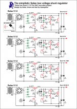
this is the schematic without the 0.1uf bypassing the 47uf.
anyway i will put the correct mosfets change the layout to make the cables shorter and use remotes and i hope i will be ok.
p.s.you are right i really need a scope.
Attachments
Hi back
Do not use C9 in V1
As you are going to use new mosfets, why not use Salas recomendations and original design ?
Do not use C9 in V1
As you are going to use new mosfets, why not use Salas recomendations and original design ?
Last edited:
Hi back
Do not use C9 in V1
As you are going to use new mosfets, why not use Salas recomendations and original design ?
i don`t use c9.
i haven`t follow the whole thread which one you suggest?
p.s. i was impressed with this one at buffalo dac.
but did it work with your buffalo dac ?
i build them for buffalo almost a year ago and they worked like a charm
with the new mosfets.
know i wanted some more for my amps input stage but something is wrong.
anyway i will wait the rest of the parts and borrow a scope.
i will figure it out.
Using a second 220r in paralel with the first 220r (R8) I got 110r for the shunt mosfet gate stopper.
Not only it is stable with the 0.047uF C1 but also the sound became much more "snappy".
A very good combination.
Now the Reflektor is a real "singer" and produces a better defined image than my revamped V1.
Not only it is stable with the 0.047uF C1 but also the sound became much more "snappy".
A very good combination.
Now the Reflektor is a real "singer" and produces a better defined image than my revamped V1.
Just 2 capacitors in the whole circuit.
I am beginning to get the impression that the fewer the capacitors the better the performance. Even amplifiers seem to be confirming this tentative conclusion.
I am beginning to get the impression that the fewer the capacitors the better the performance. Even amplifiers seem to be confirming this tentative conclusion.
And certainly cheaper, especially when avoiding an extra bypass MKP as of here example. 2N4403s are a dime a dozen also, and quiet. It will not do for BJT output well though, needs the high gfs and no Ib of the Mosfet for decent Zo. 7-35V range if Rref=7.5K trimmer. Considering Vgs+Vf and Q3's dissipation that is.
I am very pleased with the outcome 🙂
Just to finish (and close the case) I would like to add a "quality" bypass to the 1k trimmer I am using for Vref in my 10V build.
The 1k trimmer permits very fine adjustment of Vout (I can slowly adjust from 10.10 to 10.09 to 10.08 etc until I get 10.00Vout). I would like to keep this level of adjustment so the bypass should not be a very small resistor.... What should be the minimum bypass resistor value ?
Are you referring to R6? To make it adjustable. choose a slightly larger value. Say 1k2.
Now find what value of parallel resistor reduces the combination down to the original 1k0.
Here it is 6k. If the trimmer is set to 6k then the existing 1k0 load is maintained.
Use a 5k VR + 3k3 as the series pair to parallel that 1k2.
At highest setting you have 1k2//8k3 for ~1k048 and at lowest setting you have 1k2//3k3 for 880r. If these asymmetric adjustment ranges are not suitable simply change the 3k3.
For a wider range of adjustment make the 1k2 larger. For a smaller range of adjustment use 1k1 instead of 1k0, along with a 10k VR.
No Andrew, I mean paralleling a "quality resistor" in R7.
In my case, I am using R7 = 1k trimmer.
Why should I want to adjust R6 ?
In my case, I am using R7 = 1k trimmer.
Why should I want to adjust R6 ?
Don't adjust R6. Its defining some performance parameters crucial to spec. Adjust R7. ''Bypass'' with 10x R7 upwards.
Sorry the reference to 1k trimmer led me to R6.
The method I described can be applied to R7 to allow trimming.
The method I described can be applied to R7 to allow trimming.
Are you referring to R6? To make it adjustable. choose a slightly larger value. Say 1k2.
Now find what value of parallel resistor reduces the combination down to the original 1k0.
Here it is 6k. If the trimmer is set to 6k then the existing 1k0 load is maintained.
Use a 5k VR + 3k3 as the series pair to parallel that 1k2.
At highest setting you have 1k2//8k3 for ~1k048 and at lowest setting you have 1k2//3k3 for 880r. If these asymmetric adjustment ranges are not suitable simply change the 3k3.
For a wider range of adjustment make the 1k2 larger. For a smaller range of adjustment use 1k1 instead of 1k0, along with a 10k VR.
Thank you Andrew... but why do you suggest the use of a 3k3 in series with the trimmer ?
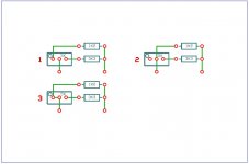
And how should I connect the trimmer ? In your 1st example I should use a 5k VR + 3k3 as a series pair to parallel the 1k2. Should I connect one of the legs of the trimmer to the wiper ?
Options 1,2 or 3 ?
Attachments
Last edited:
Correction.... I am using a 2k trimmer... Now bypassed by a 27k Holco.No Andrew, I mean paralleling a "quality resistor" in R7.
In my case, I am using R7 = 1k trimmer.
Once the final decisions have been made regarding the Vref cap´s values, I finally lost the "aligators" and soldered everything in place.
I am not sure the huge difference comes from having everything soldered or the trimmer bypass, but sound is now VERY Good indeed.
Superb delination with full tight bass suporting a delicious extended trebble.


Thank you Salas and Andrew

The existing resistor is shown as 5k2.
To make this trim-able substitute a slightly larger fixed resistor.
One E24 higher is 5k6 and two E24 higher is 6k2.
Using the higher value of 6k2 will give a bigger range of adjustment.
We need to be able to trim 6k2 down to 5k2 to get back to the original voltage setting.
The normal 2 resistors in parallel formula applies. Just re-arrange it to:-
required parallel resistor, R" = [final value, R * starting value, R'] / [R' - R] =R" = [5k2*6k2]/[6k2-5k2]=32k We would probably like the trimmer to be near midpoint when the 5k2 is set so we choose a VR ~twice that value, i.e. 64k. Use a 50k VR.
What is the lowest value you want to trim the resistance to? I'll guess at 90% of 5k2 or ~4k68
This becomes the final value R and R' still equals 6k2.
The trimmer resistor value in parallel with R' needs to be 6k2*4k68/6k2-4k68=19k1. Select the nearest value just below this, i.e. 18k. This becomes the fixed resistor in series with the VR.
We have 6k2//18K when VR is set to zero ohms and 6k2//[18k+50k] when VR is set to max ohms.
The range given by the trimmer is 4k61 to 5k68, or ~ 5k2 +9%-11%, pretty close to that +-10% target.
If you require a bigger range of adjustment choose more than 2 E24 values above the 5k2. If you require less range of adjustment choose just 1 E24 value higher.
You can fiddle about with the values all you like to get the final value and the range of values you need.
Note. Replace the 18k with 20k and rework the upper and lower trimmed resistances. Are they closer or further from the +-10% target I set for myself?
To turn an adjustable pot into an adjustable resistor, use the wiper and one end connection.
However, if the wiper goes open circuit the VR changes to infinite resistance. This can exacerbate a more serious problem. Adopt your suggested solution. Connect the unused 3rd connection the the wiper. Now if the wiper goes open circuit the maximum resistance the faulty VR can impose, is it's max resistance value. It is just possible you can arrange that this worst case situation be designed to not damage other parts of the circuit. So the answer is, yes. Connect the wiper to one end. Now the two ends are your variable resistor.
Most people expect that turning clockwise increases the adjustment. Check what end to wiper gives maximum resistance when the adjustment is turned fully clockwise. Insert it in the circuit such that clockwise adjustment gives maximum in circuit resistance.
BUT.
Sometimes you want the adjusting "effect" to increase with clockwise rotation. This may require the resistance to go down to increase the circuit "effect". A Vbe multiplier is just such an example. When the VR is across the BE junction a smaller resistance gives a higher Vbe voltage at the output and this leads to a higher output bias current. This is where you would ensure you put the pot in back to front to get clockwise = minimum resistance.
Last edited:
- Status
- Not open for further replies.
- Home
- Amplifiers
- Power Supplies
- The simplistic Salas low voltage shunt regulator