What current do you assume to be passing the jFET Q9?
27k for a 5V output sounds mad ! That would require q9 current ~160uA
I would expect a 1k trimmer (Vr for R10) to be about right for 5V output.
R6 is designed to have 2.8mA passing. That determines the required resistor value.
Post 3807 schematic. R6 in is Q6 EF's emitter resitor. Sees Vout-Vgs. In very low Vout is good not to go under 1.8-2K, to lose some running current for the follower is better than to unload it, risking instability. The trimmer is R9 and the Vref resistor is 27K R10. 1K Vr is OK as in the schematic, but 5K Vr also has trim when needing very low running current through R10 for going very low Vout. Cant't hurt. Q7 has 1K R10 base resistor and requires very low base current anyway. Most 5V builds reported here had 27K I think. Filters easier by 4u7.
V1.1 revision in progress
Maybe the keener of the thread participants remember a CRT's trial on a film caps using reg board I gave him a schematic for, called 1.1. Its a faster finer TO-220 remote sense only SSSR. It was integrated to a an I/V DAC of his with excellent results, had shown a picture once here. We recently cooperated in much consultation so to produce a test board in double layer plated through thick profile & heavy copper. We finished just yesterday including all Vref and hot rod features I integrated, 2 samples had been ordered from fab house in fool tooling expense and best quality between Tea Bag and me. Since the colour will be black I nicknamed the layout BackInBlack.😀 To commemorate our first Hypno & Mez in black and to continue in the Rock themed names vein. I will test and refine, will scope and listen, and if I feel its good I will write a full instructions and BOM PDF for it. Then it can be released for GB if Tea Bag wants to undertake it so to have an available PCB in best quality, with enough communication and reference documentation for all. Will let you know, will take some weeks only to get samples.
Maybe the keener of the thread participants remember a CRT's trial on a film caps using reg board I gave him a schematic for, called 1.1. Its a faster finer TO-220 remote sense only SSSR. It was integrated to a an I/V DAC of his with excellent results, had shown a picture once here. We recently cooperated in much consultation so to produce a test board in double layer plated through thick profile & heavy copper. We finished just yesterday including all Vref and hot rod features I integrated, 2 samples had been ordered from fab house in fool tooling expense and best quality between Tea Bag and me. Since the colour will be black I nicknamed the layout BackInBlack.😀 To commemorate our first Hypno & Mez in black and to continue in the Rock themed names vein. I will test and refine, will scope and listen, and if I feel its good I will write a full instructions and BOM PDF for it. Then it can be released for GB if Tea Bag wants to undertake it so to have an available PCB in best quality, with enough communication and reference documentation for all. Will let you know, will take some weeks only to get samples.
Attachments
Interesting news Salas.
Can you anticipate the schematic?
If a PCB is going to be manufactured some day, two scoring lines will be welcomed by who might need one or two SSSR only (or want to use the three regs in different boxes)
P.S. Why the lefthand part is reversed? Negative side?
Can you anticipate the schematic?
If a PCB is going to be manufactured some day, two scoring lines will be welcomed by who might need one or two SSSR only (or want to use the three regs in different boxes)
P.S. Why the lefthand part is reversed? Negative side?
Not to mention a DCB1 MkII with V1.2R 😉It was time for that Salas!
Interesting news Salas.
Can you anticipate the schematic?
If a PCB is going to be manufactured some day, two scoring lines will be welcomed by who might need one or two SSSR only (or want to use the three regs in different boxes)
P.S. Why the lefthand part is reversed? Negative side?
V scoring is already specified along the sections. There are two positive and one negative polarity sections. The final schematic and BOM will be defined after finishing.
It was time for that Salas!
It was a Crt's initiative push. He enjoyed his and was confident. Something with more resolution than V1.0 but along the lines of its practicality, not needing the learned fixes of 1.2R for each one voltage and current applications. And a more configurable Vref. An evolved classic SSSR in other words.
Not to mention a DCB1 MkII with V1.2R 😉
A Salas approved PCB for SSHV would be nice too!
Not to mention a DCB1 MkII with V1.2R 😉
Not easy to build in DCB1 some further coherent quality, its voiced with its regs and has its stamp as a dynamic THD profile. Maybe a test in the future with different audio cell. I like the late great John Linsley Hood's heritage in CFP Jfet-Bjt buffer style. That would need to be tuned with differentiated regs also most probably.
No..... or select two Mosfets with similar Vgs. 😉
You miss the point, that being that Vgs varies with Id. You cannot change that, ever.
Are you serious? Recommending ~160uA through R10 and it's CCS for a 5V output?Post 3807 schematic. ............The trimmer is R9 and the Vref resistor is 27K R10. 1K Vr is OK as in the schematic, but 5K Vr also has trim when needing very low running current through R10 for going very low Vout. Cant't hurt.
The base current of the BJT is probably <2uA when idle. Leading to ~162uA through R10.
This 2uA base current will vary enormously, when Q5 demands fast changes to minimise the HF noise that we don't want on the output.
Last edited:
Other way is 2.7K R10 resistor, 220R VR and 47u elco cap. Take your pick. As far as I know, 5V regs have been made with the 27K and were reported OK. Just because it was there in the 15V designs. 1uA variation in 162uA total is 0.62%. BC550C max hfe sample for 5Vo is best.
Thus I was simply lucky. I always selected mosfet by their Vgs and resistors and got coherent results (read: very similar current) between different regs.No.
You miss the point, that being that Vgs varies with Id. You cannot change that, ever.
there is nothing wrong with selecting mosFETs by Vgs.Thus I was simply lucky.
You are still missing the point.
He asked if the voltage across the resistor changes when he alters the resistor value.
The answer was YES.
The reason is that Vgs varies with Id.
Selecting Vgs can never stop that change in Vgs happening when he tries a different value resistor.
Hi Salas,
I finally build my first 1.2R 5V, but it just oscillates badly. To avoid low ESR, my C1 & C3 are BG NX 4.7uf/50V. C2 is Panasonic FM 47uf(Try Silmic too). I even put a 0.22R in series with C2, but no help at all. Vin=12V, R1=4.7R, Q1=IRF9610, Q5=IRF9540, Q3=2N5458 Idss 6.5ma, Q8=2SK170BL.
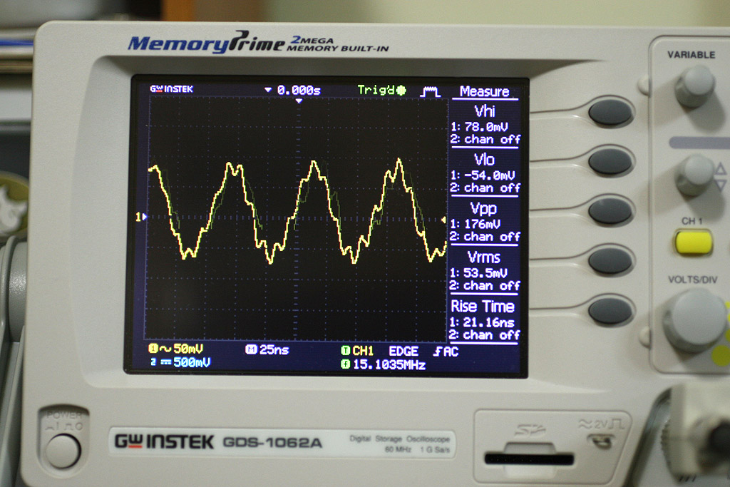
It oscillates at 15Mhz.
Vin is from my linear power supply. The current is 164ma with 12V in.
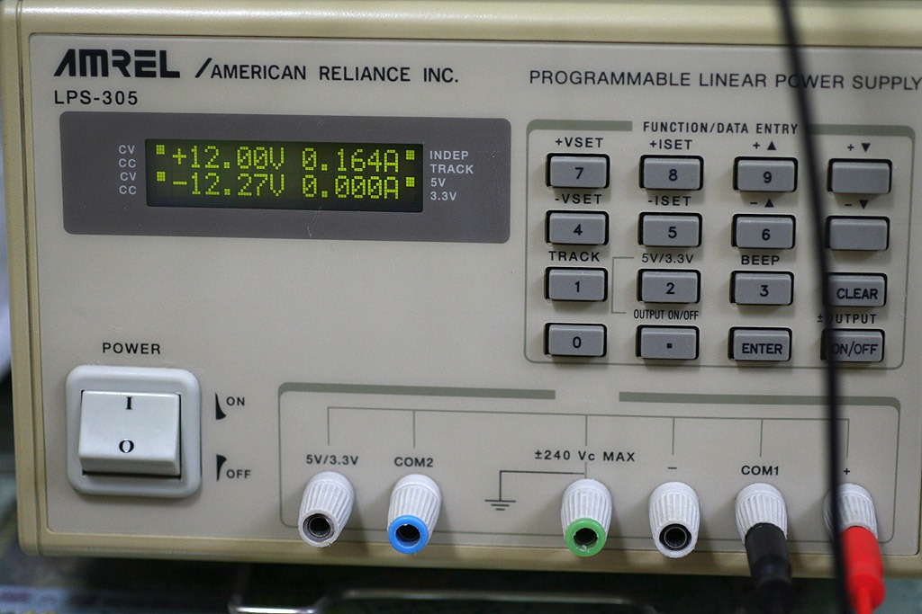
Vout is adjustable. Without a scope, it looks ok to me.
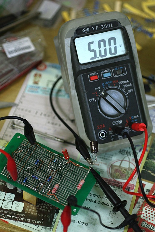
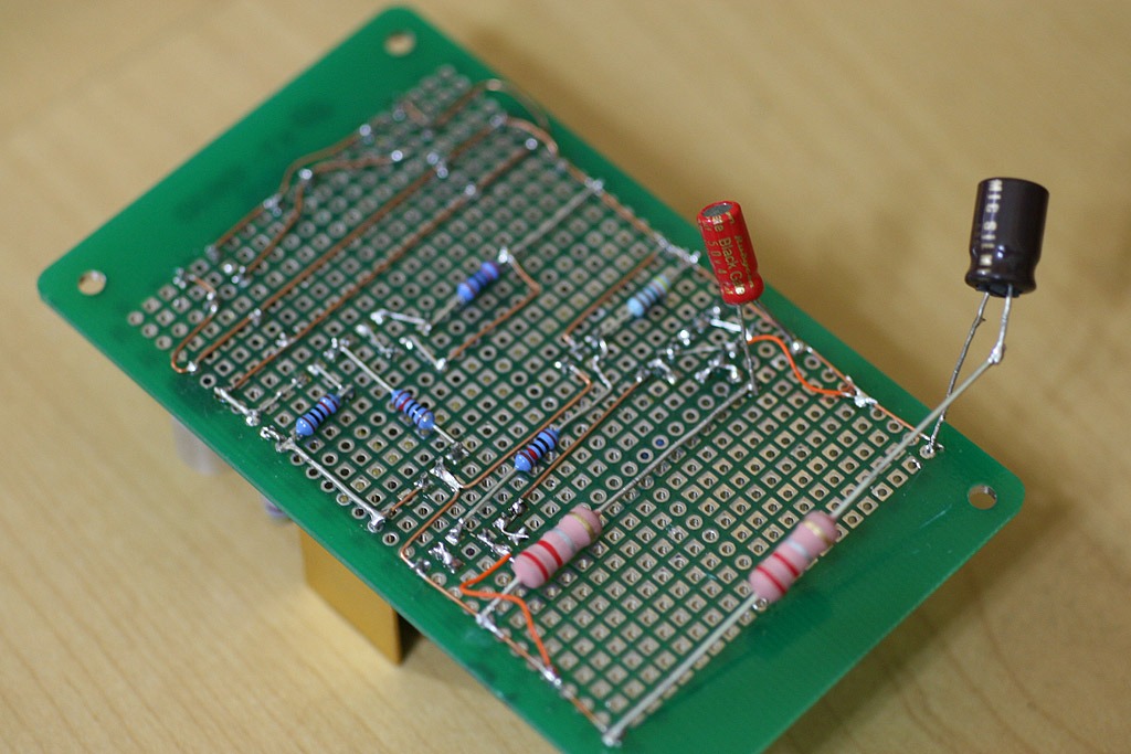
Front.
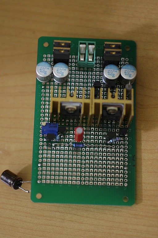
Rear. Orange wires are the sense cable.
Any suggestion?
I finally build my first 1.2R 5V, but it just oscillates badly. To avoid low ESR, my C1 & C3 are BG NX 4.7uf/50V. C2 is Panasonic FM 47uf(Try Silmic too). I even put a 0.22R in series with C2, but no help at all. Vin=12V, R1=4.7R, Q1=IRF9610, Q5=IRF9540, Q3=2N5458 Idss 6.5ma, Q8=2SK170BL.
It oscillates at 15Mhz.
An externally hosted image should be here but it was not working when we last tested it.
Vin is from my linear power supply. The current is 164ma with 12V in.
Vout is adjustable. Without a scope, it looks ok to me.
Front.
Rear. Orange wires are the sense cable.
Any suggestion?
Last edited:
Make a schematic by following your build's connections, see if there is a mistake in the execution or in some value. Show it here too. Does it have a dummy load when measuring? Are the 2 Mosfets fully isolated? Gate stoppers really near to gates? R8 1K? 1.2R is easy to tame, lets debug. Nice and clean work by the way.
I tried v1.2 with 9540 and was not working. Don' t remeber exactly what happened, but changed back to 9140 and everything was fine again. Mine was 52v in 43v out. I don' t remember somebody done v1.2 with 9540. Maybe the higher input capacitance?
- Status
- Not open for further replies.
- Home
- Amplifiers
- Power Supplies
- The simplistic Salas low voltage shunt regulator