Make a schematic by following your build's connections, see if there is a mistake in the execution
First things first are always a good check.
Looking to the most basic things and never getting frustrated when debugging is the lesson once more.
Code:
...(errarem umanum est)When this is supposed to be latin it should go like 'errare humanum est'...
no pun intended 😉
hey,
I connected a Salas super reg red boards to my shinga clone and it just wanted to pulse the power,I grabbed a meter and it was all over the place I did set it at 8 vdc before I connected it and the sense wire were connected at the terminals,it was working fine on other boards,does it not like motors?
Thanks!

hi Salas,
I put the lm reg back on it,on it works fine I believe it was changing the load and the reg was reacting to it and just not fast enough to out run it,lol.
I will build a 5 and 8 volt reg and see how that looks!
I'll put yours back on the electronic stuff where it does it's job!
Thanks for responding!
Have a GREAT Day!
Thank you, everyone. I guess I was lucky that nothing was burn or damaged! It's very easy to make mistakes since I am viewing the board upside down while soldering. Anyway, the result is great. As the power for TCXO in my player, it's absolutely better than low-noise Onsemi TL431+bjt setup. I can hear more details and every instrument can be clearly identified. The Hi, mid and low tones are well-balanced. Never get exhausted while listening for hours. Starting to build another one for my OCXO from the DAC, will report back soon.
Last edited:
Happy end. Congratulations. Do you use the remote sensing scheme? Take some pictures installed if you like also.
hi Salas, where I've to look at if I want a +/- 24V out 1.2 r?
Looking at post 3200 , I think I've to use the 3rd and 4th schematic. It's the Jfet CCS cascode the limit over 24V out? The Bjt cascode is mandatory?
thanks
Looking at post 3200 , I think I've to use the 3rd and 4th schematic. It's the Jfet CCS cascode the limit over 24V out? The Bjt cascode is mandatory?
thanks
Last edited:
hi Salas, where I've to look at if I want a +/- 24V out 1.2 r?
Looking at post 3200 , I think I've to use the 3rd and 4th schematic. It's the Jfet CCS cascode the limit over 24V out? The Bjt cascode is mandatory?
thanks
The Jfet cascode will do 28Vin max.
Hi Salas,
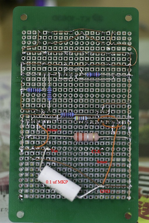
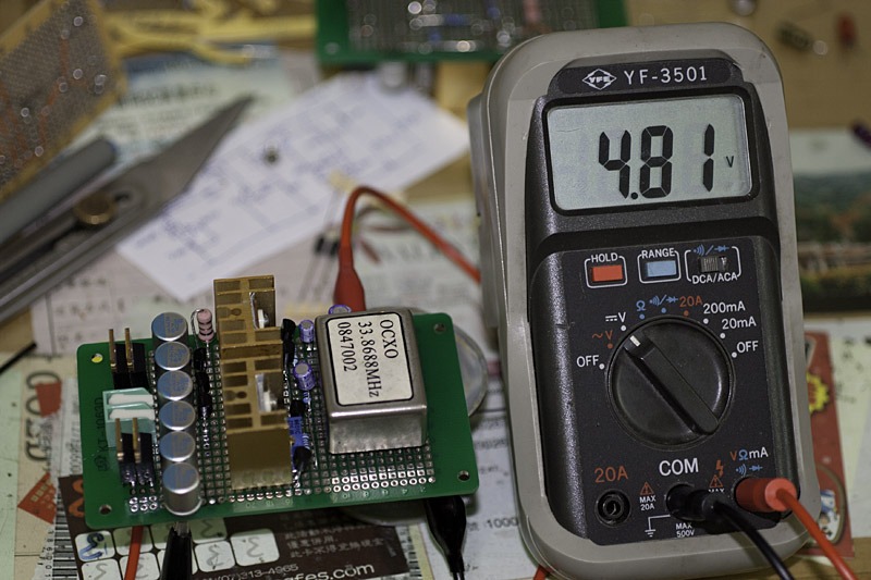
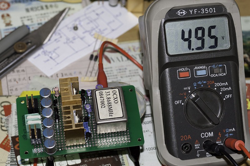
I made another 1.2R for OCXO. Here is the photo of the sense scheme shown in #1. I haven't judged its performance since I got another problem. The voltage drift is quite high as you can see from #2 & #3. Photo #2 was taken just right at the power on. And #3 shows the volatge drift after 20 minutes. I've been reading lots of the post here. It seems the size of the heat sink does matters.
#1
#2
#3
After it goes 4.95V is it stable then on? Use a smaller resistor than 27K. Say 10K. See how is your drift. You can also add an LED at the base of that resistor in series. Cathode to the JFET. It will show ''on'' and may help with the TC a bit also.
Salas,
I will definitely try that. However, the drift seems to be strongly related to the temperature of IRF9540. If 9540's heatsink is touched by any cold material, the vout will drop instantly.
I will definitely try that. However, the drift seems to be strongly related to the temperature of IRF9540. If 9540's heatsink is touched by any cold material, the vout will drop instantly.
With small sinks the temp rises a lot, Vgs changes. TC of nearby parts on tiny board also changes. You follow the chain of events. By making the Ref resistor smaller and readjusting the trimmer, we hope we go to easier region and slower I/V change reactions. Lets see. Try 6K8 also if the drift shows like narrowing. How much current do you use on your load by the way? We may even run it colder as a whole.
- Status
- Not open for further replies.
- Home
- Amplifiers
- Power Supplies
- The simplistic Salas low voltage shunt regulator