New simplistic Salas shunt regulator V1.2R
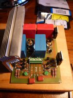
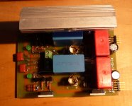
Hey, I finished the first reg V1.2R, a photo just for fun
Hey, I finished the first reg V1.2R, a photo just for fun
An externally hosted image should be here but it was not working when we last tested it.
Hello,
I was thinking if I put the ccs in cascode I can increase the total current and would have other benefits. Is this right?
Can I put on input a capacitance multiplier to increase the PSSR with TIP142?
I was thinking if I put the ccs in cascode I can increase the total current and would have other benefits. Is this right?
Can I put on input a capacitance multiplier to increase the PSSR with TIP142?
In practice cascoding the CCS Mosfets does not help as much as with the already cascoded tail for the CCS control. I much prefer the multiplier before. More drastic. Plus it needs less drop to work.
@RCruz
Ricardo, still not, I'm waiting to finish the 2nd reg to fire both with the phono🙂
@Salas
Thanks for the input, I will do, only do separate terminals to test purpose😉
Ricardo, still not, I'm waiting to finish the 2nd reg to fire both with the phono🙂
@Salas
Thanks for the input, I will do, only do separate terminals to test purpose😉
Is it the 120R away from shunt Mosfet's gate, or is it underneath? Both Mosfets must be intimate to their gate resistors. Its loose layout as a whole. I hope it will still work.
Yes you are right are both far, so I can connect the gate resistors directly to the mosfets, thanks again.
Salas,
Built the V1.2R, but can't seem to get the negative side up and running. The diode is quite dim. 69v in 4.1 vout. I've attached my schematic with measured voltages. I've already replaced the diode and Q9, double checked solder joints and resistor values. Your thoughts?
Thanks
Ken
Built the V1.2R, but can't seem to get the negative side up and running. The diode is quite dim. 69v in 4.1 vout. I've attached my schematic with measured voltages. I've already replaced the diode and Q9, double checked solder joints and resistor values. Your thoughts?
Thanks
Ken
Attachments
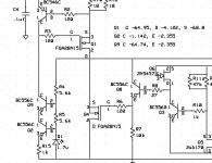
I suspect the Shunt is shunting too much current and pulling down the output voltage.
Remember I warned about considering the R4:R5 ratio.
You now have >60Vce on the cascode.
Disconnect everything on the shunt side and see if the CCS side works properly.
Remember I warned about considering the R4:R5 ratio.
You now have >60Vce on the cascode.
Disconnect everything on the shunt side and see if the CCS side works properly.
Salas,
Built the V1.2R, but can't seem to get the negative side up and running. The diode is quite dim. 69v in 4.1 vout. I've attached my schematic with measured voltages. I've already replaced the diode and Q9, double checked solder joints and resistor values. Your thoughts?
Thanks
Ken
The LED is dim since there is little Vo that is fed from. Make that BC546 a BC550C. 4.1Vout means just Vgs. There is no Vref functioning. See about Q3, Q6 correct practical orientation or being busted. Check correct JFET connections. Check its alive. I don't see that circuit part in your pic clip.
Salas,
I will follow your suggestions. I've reposted the schematic with the actual resistor values shown, the prior one hadn't been updated. I forgot to mention that the positive version is running with vout at approx. 60v with R11 set at 12k.
Ken
I will follow your suggestions. I've reposted the schematic with the actual resistor values shown, the prior one hadn't been updated. I forgot to mention that the positive version is running with vout at approx. 60v with R11 set at 12k.
Ken
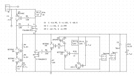
You miss a connecting line between S & G of Q5. If you miss it for real, you got no Vref.
Thanks you Salas!
Did you make new R PCBs or modded the 1.2? Also is the positive side steady and oscillation free? Any pic to see the layout?
Did you make new R PCBs or modded the 1.2? Also is the positive side steady and oscillation free? Any pic to see the layout?
Yes, I made new R PCBs, the positive side is steady though haven't checked for oscillations yet. Photos coming soon.
Nice. Check it all works steady and giving straight scope lines. Will be happy to know it all went OK since you use strong voltages and non used before Mosfets and layouts. Enough differences right from the start. If it will be success without many changes for both +/- regs, it will mean 1.2R is very elastic.
Any pic to see the layout?
A few pics, not the best lighting...
Attachments
- Status
- Not open for further replies.
- Home
- Amplifiers
- Power Supplies
- The simplistic Salas low voltage shunt regulator