I imagine Mr. Salas years from now, in his 70s, slowly walking up mount Athos, and this young guy running behind him: "Mr. Salas! Mr. Salaaaas! How do I set the idle current? ... and what about those sense wires?" 😀
We've all been there. I reminded myself of my 4 year old at times. "Mr Salaas! Sorry to bother you again, but I have a list of questions for you:"
🙂
Hey, I've bugged Salas with endless questions myself too 😀 If he got a penny for every answer he gave...
😀😀😀
Attachments

Hi,
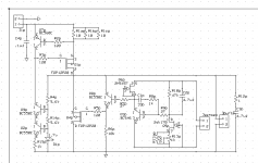
a few errors on the schematic pic.
Two LEDs are very unlikely to give 5V output.
You need a third LED (voltage a bit too high) or a resistor to bring the output voltage up to what you need.
Q1 dissipation is Idq1 times [Vin-Vout] for 10V input, that comes to 15W.
If Vin rises to 12V then dissipation rises to 21W.
Can the input voltage drop below 10V? This leaves a small margin for Vdrop across the CCS. The recommended minimum CCS Vdrop is 6V and usually we are told to aim for 10V to allow for mains variations and transformer regulation.
They were specified to 2.2Vf when that schematic was communicated. Hence 5V possible taking one Vbe into account. If not such greens to find and with 1.9Vf, add a diode.
R1 drops 2V, hence circa 10W for Q1 with possible tolerances.
I would stay on safe side at 8-10V. But minimum could be tested for individual AC mains statistics.
R1 drops 2V, hence circa 10W for Q1 with possible tolerances.
I would stay on safe side at 8-10V. But minimum could be tested for individual AC mains statistics.
my mistake....R1 drops 2V, hence circa 10W for Q1 with possible tolerances....
You are right.
5W to 6W dissipated in the resistor!
Perhaps instead of an epitaph, we can simply upgrade DIYAudio to become DIYAudio-Matrix, so when we go to the shunt reg section, you're brain is hard wired into it and kept alive with small donations and the odd glass of lemonade.
It's a bit rough on you Salas, admittedly, but we'll be able to feed off it with our insatiable appetite for tweeks, mods and calculations for generations to come! 😀
Questions will be more like:
"Mr. Salas, My dad's broken old pre-amp seems to have a ton of small lights on it, and some of them aren't lighting up. What's the deal? As a child I remember him swearing at this thing for days, and then raving on about "listen to that midrange, son!" I'm a bit of a noob - will I need a multimeter to sort it?" Aaaaaaargh! 😀
Hey, I've bugged Salas with endless questions myself too 😀 If he got a penny for every answer he gave...
I'm the winner, for sure I haven't got a lot of money to pay him...
Coax or twisted, the ground side is attached on sense pcb ground and at load ground. Pcb sense connections meet force connections only at the load.
Geeze, who would have thought... one small question 😱
Here's my schematic; positive reg v1.2 50 to 60v out R13ap will be installed and R13p removed for final voltage setting. The sense and load will meet at the load. Comments please 🙂
Ken
Attachments
Looks OK. Only position the Jpwr and R12p, C3p near Q4p in layout. Also use as system ground point the C3p's ground point.
Some questions!
Now I have placed 47R resistor nearer to the base of Q3 and I have placed two holes for sense wiring, one right next to the Q2 and one is at the bottom of Q5.
Now some questions:
1. In short what would be the problem if I omit sense wiring (the wire from PSU to the SB would be about 1m long)?
2. How to reduce the load current to about 1.8A or what is the formula like for calculating the load current?
Regards Aleš
Attachments
You did not create remote sensing with those 2 holes. Watch the circuit diagram, the whole control circuit is hanging on air and meets the power circuit with wires at the load. You need to cut it off too in other words.
1. Sound quality full potential loss, no electrical problem.
2. Total drop of Leds-Vgs=VR1. VR1/R1=ICCS.
1. Sound quality full potential loss, no electrical problem.
2. Total drop of Leds-Vgs=VR1. VR1/R1=ICCS.
Hey Salas, I'm still a little unsure about the best way to proceed with the supplies for my 2x TDA1541A DAC project. The DAC boards Oliver has made up have already got TL471A shunt regulators near to the chips, which are fed, via 2x Os-Cons from Salas shunt regs. The reason that Thortsten Loech advised to put TL471As in there, I believe, was because Oliver was talking about implementing up to 4x DAC chips in parallel, each supplied by single shunt regs, and Thorsten said that was not a good idea without TL471s.
I know that if I were working on a single chip DAC, I wouldn't hesitate to remove the secondary shunt regs, but what about with 2 DACs? What happens when you supply 2x loads from the same Salas shunt reg? Thorsten said that he was not familiar with the Salas reg, but that in general this is a potential source of jitter. Is it likely, in your opinion, that I would get more jitter supplying 2x boards directly from Salas regs? What nodes could I implement to reduce this?
I know that if I were working on a single chip DAC, I wouldn't hesitate to remove the secondary shunt regs, but what about with 2 DACs? What happens when you supply 2x loads from the same Salas shunt reg? Thorsten said that he was not familiar with the Salas reg, but that in general this is a potential source of jitter. Is it likely, in your opinion, that I would get more jitter supplying 2x boards directly from Salas regs? What nodes could I implement to reduce this?
I can't say what's best for the client circuit with any authority. In general when the output impedance of a power source is very low it will not allow client loads to interact by imposing changes with their dynamic draw since there will be no appreciable resistance to dance their drawing currents on. That is dynamic isolation. Using individual local regs of even more Zo is physical isolation. I don't know if the TLs are noisier than a V1 or not, also. You should listen with and without I suppose.
OK. I guess I will make it as stock then, and leave such experimentation for when I have time.
In other words, when it's all working well, I'll break it in order to mend it again. That's DIY! 😀
In other words, when it's all working well, I'll break it in order to mend it again. That's DIY! 😀
Stability
Hi Salas,
I have tried to figure out how to check the stability margins on you super shunt regulator by simulation, but, alas, could not find out how to do it. 😕
Would you please explain how to simulate stability margins (phase margin for ex) on you regulator?
Regards,
Ingemar
Hi Salas,
I have tried to figure out how to check the stability margins on you super shunt regulator by simulation, but, alas, could not find out how to do it. 😕
Would you please explain how to simulate stability margins (phase margin for ex) on you regulator?
Regards,
Ingemar
You need to look for LT Spice ways for simulating amplifiers. Its a whole methodology. Read there a bit.
Attachments
Hello Salas.
Could you post the LTSpice files for this simulation? I would like to play with the compensation and test the circuit's stability.
- keantoken
Could you post the LTSpice files for this simulation? I would like to play with the compensation and test the circuit's stability.
- keantoken
I will send it to you by email because it gives me a hard time accepting it as it is or as .zip PM me your email.
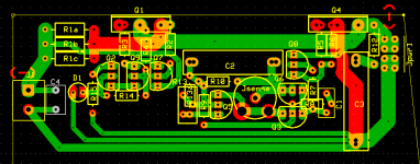
As per Salas, suggest move input J1 to lower edge of brd about midpoint (roughly below the present R13) Will probably need to increase the "vertical" distance (height?)
At the same time, consider using that vacant area between the Q1 and Q4 as a convenient point for the output pins (it doesn't have to be a traditional +/- connector at all) and so the 0volts points are neatly together at the bottom edge of the pcb - will also need to move the R12 + C3, unfortunately.
Random other thoughts - R15 could fit neatly between Q2,Q9 and, D1 could do with a cap across it (IMO, that is) and the "Jsense" point is a bit confusing.
Perhaps, also move the resistors R4, R5 a bit further away from the Fet pins and you might consider adding the option to connect the R6 closer to the central 0volt point rather than directly to the Fet - not sure if any advantage, but just another donut
This will give a more compact, shorter track version but the "more square" board may not suit your requirements.
None of these comments may be of any use to you, and it's good to see your design - good fun, this!
my 2 cents ...
- Status
- Not open for further replies.
- Home
- Amplifiers
- Power Supplies
- The simplistic Salas low voltage shunt regulator