You probably mean low voltage, not SSHV. What are the conditions of measurement, what those charts represent? You capacitor coupled the DC and fed an FFT, or is it the noise floor of some audio circuit supplied by such a reg?
You probably mean low voltage, not SSHV. What are the conditions of measurement, what those charts represent? You capacitor coupled the DC and fed an FFT, or is it the noise floor of some audio circuit supplied by such a reg?
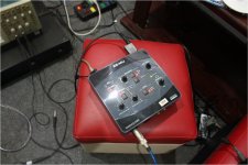
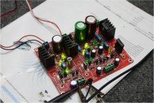
Yes! Salas low shunt, I mesuare at 5 v and 3.3V
I see Bd140 it the best ad 3.3v, better than Mje350
That is macsin for measure!
Attachments
I recommended BD140, I know. My questions were about the method of measuring not what was measured. What your charts represent? Noise floor of the card on top chart, and AC coupled noise floor of the regs outputs below? Also what kind of current you run for the tests, because I see no sinks.
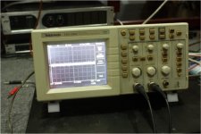
Through my sound meter directly to Cad D404 SShv low with computer software, with a total load 66ma! Partly because of noise measurement instruments, the Vietnamese called the * Ù nền* - noise of machine I do not know this world by English !
Special Bd140 at 3.3 V is very good, better in 5 v. distributed by a noise meter is also involved (ù nền) Ground noise may be it is)
I do not know how to describe you understand the difficult hard too!
I do not know how to describe you understand the difficult hard too!
Residual noise of ground and measurement loop you probably mean. OK, thanks QH.
Yes! SSHV low, it is very good at 3.3V!
Hello!
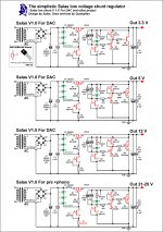
After I tested at Salas shunt voltages from 3V to 25 v. I found it great, suitable for various projects such as DAC, Clock, Pre, Phono. I sum up all in a drawing back, there's nothing wrong on the schematic hope you showed me! Thanks!
After I tested at Salas shunt voltages from 3V to 25 v. I found it great, suitable for various projects such as DAC, Clock, Pre, Phono. I sum up all in a drawing back, there's nothing wrong on the schematic hope you showed me! Thanks!
Attachments
Regulators for the Classic Pass Labs D1 with an ESS Dac
@Salas
Please for the new Classic Pass Labs D1 with an ESS Dac we need your design for Vin 60V & Vout 50V / 250mA could you help us?
@Salas
Please for the new Classic Pass Labs D1 with an ESS Dac we need your design for Vin 60V & Vout 50V / 250mA could you help us?
Hello!
After I tested at Salas shunt voltages from 3V to 25 v. I found it great, suitable for various projects such as DAC, Clock, Pre, Phono. I sum up all in a drawing back, there's nothing wrong on the schematic hope you showed me! Thanks!
As I said before can not connect the sense with the force, you must added 2 holes for sense output + & -
Hello!
After I tested at Salas shunt voltages from 3V to 25 v. I found it great, suitable for various projects such as DAC, Clock, Pre, Phono. I sum up all in a drawing back, there's nothing wrong on the schematic hope you showed me! Thanks!
For 3Vout you must use other CCS & change/eliminate some resitors😉
@Salas
Please for the new Classic Pass Labs D1 with an ESS Dac we need your design for Vin 60V & Vout 50V / 250mA could you help us?
Sorry Salas, don't need help because I see in the last schematic the Vout +-45 like the regs I'm using in my Simplistic NJFET phono RIAA only have to change for the negative rail the mosfet to IRFP140 & BC556B, finally will be two +-45Vout & one +5Vout
Is this pcb ok?
Hi guys!
I decided to make PCB on the Squeeze shunt regulator and I would like to know if the way it is is going to work. The markings are the same as in the scheme.
Don't want to burn anything.
Regards Aleš
Hi guys!
I decided to make PCB on the Squeeze shunt regulator and I would like to know if the way it is is going to work. The markings are the same as in the scheme.
Don't want to burn anything.
Regards Aleš
Attachments
I know this has been answered before, but, this thread is pretty long...
The sense wire; it is coax, and the ground screen is attached at the shunt board, is it also attached at the load end as well?
Thanks
Ken
The sense wire; it is coax, and the ground screen is attached at the shunt board, is it also attached at the load end as well?
Thanks
Ken
mravlaca:
In a quick look seems OK, though the 47R is supposed to go near the Q3's base. Keep it near the SQB since you did not opt for remote sensing 4 wire arrangement as in the CCT you referred to.
In a quick look seems OK, though the 47R is supposed to go near the Q3's base. Keep it near the SQB since you did not opt for remote sensing 4 wire arrangement as in the CCT you referred to.
I know this has been answered before, but, this thread is pretty long...
The sense wire; it is coax, and the ground screen is attached at the shunt board, is it also attached at the load end as well?
Thanks
Ken
Coax or twisted, the ground side is attached on sense pcb ground and at load ground. Pcb sense connections meet force connections only at the load.
I imagine Mr. Salas years from now, in his 70s, slowly walking up mount Athos, and this young guy running behind him: "Mr. Salas! Mr. Salaaaas! How do I set the idle current? ... and what about those sense wires?" 😀
lol. He'll have to have those vital pieces of information as his epitaph.
I imagine Mr. Salas years from now, in his 70s, slowly walking up mount Athos, and this young guy running behind him: "Mr. Salas! Mr. Salaaaas! How do I set the idle current? ... and what about those sense wires?" 😀
I imagine Mr. Salas years from now, in his 70s, slowly walking up mount Athos, and this young guy running behind him: "Mr. Salas! Mr. Salaaaas! How do I set the idle current? ... and what about those sense wires?" 😀
We've all been there. I reminded myself of my 4 year old at times. "Mr Salaas! Sorry to bother you again, but I have a list of questions for you:"
🙂
- Status
- Not open for further replies.
- Home
- Amplifiers
- Power Supplies
- The simplistic Salas low voltage shunt regulator