Correction, only the D3 (Grn) and D6 (Yel) are not working. The Red <Fault> are both working fine... BTW I wonder how D6 can light with R12 at 100K, there won't be enough current to drive the led, isn't?
D3 should work though. Will look ore closely at D3, maybe a soldering problem... No, checked and everything ok. D3 needs 1.8V to turn on (Green led), but the maximum accross D3 is 0.7V (Q4 Vbe, when the relay is On), or close to +Vs when off, so there is never more than 0.7V accross D3, so it never turns on. Solution?
Thanks
SB
Last edited:
Nothing to worry.
They are not supposed to turn on.
They are just there as a safeguard.
Nothing wrong with the circuit.
Tens have been built.
Just follow the functionality test to verify all working as intended.
Patrick
They are not supposed to turn on.
They are just there as a safeguard.
Nothing wrong with the circuit.
Tens have been built.
Just follow the functionality test to verify all working as intended.
Patrick
Take a look here and the posts after :
http://www.diyaudio.com/forums/head...-simple-headphone-protection.html#post5233155
Patrick
http://www.diyaudio.com/forums/head...-simple-headphone-protection.html#post5233155
Patrick
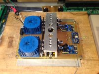
Complete amp prototype working, with the actual assembly, the output DC offset settled at very low values, 5mv and 3mv. No need to tweek the CCS, and/or the supply regulator output voltages. It is pretty stable, quite impressive.
BTW my regs heatsink is not too big, it is warm to the touch. In the enclosed chassis everything will easily stabilized at least 35C...
Time to work on the Volume pot/crossfeed PCB
BTW my regs heatsink is not too big, it is warm to the touch. In the enclosed chassis everything will easily stabilized at least 35C...
Time to work on the Volume pot/crossfeed PCB
Attachments
> Complete amp prototype working, with the actual assembly,
Many congratulations. Very fast progress, unlike us. 🙂
> the output DC offset settled at very low values, 5mv and 3mv.
Because you are using both CCS and servo.
You will find (as we did) that when you use CCS only, you can trim and then there is no more need for servo.
But it is personal taste. I try to get rid of servo if I can.
> BTW my regs heatsink is not too big, it is warm to the touch. In the enclosed chassis everything will easily stabilized at least 35C...
I consider 35°C to be very low for Class A.
In the example I showed earlier, the AL angle is connected to the bottom (aluminium) plate via brass standoffs.
The latter in turn is connected to the side heatsinks of the 2107 case.
So the heat dissipation has an additional path to the side heatsinks.
> Time to work on the Volume pot/crossfeed PCB
That will take you no time. 😉
Patrick
These DC offset numbers are without the servo, I didn't install the Servo parts, since I was using the CCS...
Cross Feed/Volume pot connection questions:
Q1: If I understand the small cross feed pcb, the small On/Off pads for a jumper/switch turns on/off only the Cross Feed effect, but leave the treble boost network in circuit?
Q2: I don't see soldering pads for the Volume pot to the amp input, or are we using the unused pot pads for this purpose?
Q3: The small pcb input marked Fi, should be Li, insn't?
To resume, from the rear RCA inputs, up to Ri/Li pads on the Crossfeed PCB, and then the volume pot middle wiper pads up to the amp inputs, right?
> These DC offset numbers are without the servo, I didn't install the Servo parts, since I was using the CCS...
Then your matching is very well done. 😉
Q1: If I understand the small cross feed pcb, the small On/Off pads for a jumper/switch turns on/off only the Cross Feed effect, but leave the treble boost network in circuit?
Correct, but the boost is really minimal.
The switch is there for you to make a quick comparison between XFD and no XFD.
Once you decide that you do not want XFD, you want to remove the entire board anyhow.
Q2: I don't see soldering pads for the Volume pot to the amp input, or are we using the unused pot pads for this purpose?
I normally solder the amp input wiring directly on the pot pins.
> To resume, from the rear RCA inputs, up to Ri/Li pads on the Crossfeed PCB, and then the volume pot middle wiper pads up to the amp inputs, right?
Correct, plus Gnd wires of course.
And use twisted pair for each channel.
Patrick
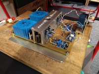
Well, it's done, the prototype is playing. First impressions:
-Perfectly silent, even without an enclosure, and at full volume, impressive
-First listening test using one of the best recording I ever know, StockFish Records, Closer to the Music - Vol.1, Hires file. First class headphone amp! WOW 😱
This gear is making real music, and the Xfeed is a keeper, it sounds just perfect all over the band, great bass, gorgeous mids, and crystal clear highs. At least that's how my reference source sounds, and this headphone amp delivers the music right at your ears.
This little amp is probably ones of my best, reference class 😀
Can't wait to mount it into an enclosure.
Very well the investment in parts and time 🙂
Thanks Patrick and the Xen Audio team for sharing such great design!
Attachments
Another satisfied customer. 🙂
But this time you have to thank Mr. Ozawa.
For Zero Global Feedback (ZDF) Headamp, this would probably a equal second on my own list.
Cheers,
Patrick
But this time you have to thank Mr. Ozawa.
For Zero Global Feedback (ZDF) Headamp, this would probably a equal second on my own list.
Cheers,
Patrick
this would probably a equal second on my own list.
That makes it three of us, then. 😉
Nice work SB, chapeau!
The UTHAiM has a slightly different signature, and has great current delivery.
So it will excel on current-hungry but not bass-heavy headphones such as AKG K701s.
The SL is very even over the frequency band.
BUT the DAO just have that magic. (See Stixx's review earlier.)
What speaks for the SL is of course all components are easily available at reasonable costs.
The DAO uses only unobtaniums en masse, and hence will cost a small fortune.
😉
Patrick
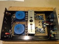
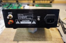
Completed the built, all done now. The chassis was probably designed for a small Class-D amplifier, hence the ventilation holes on the top. It was perfect for the SLHA. Once warmup, inside and bottom cover temperature is 36C, the regs heatsink is 41C, nice and cooking as a Class-A amp should be 😉
An other happy Diyer, see the pictures...
An other happy Diyer, see the pictures...
Attachments


Last edited:
For 2SA1312/2SC3324, why the choice of BL grade? The BL grade, both polarities, has hFE of 350-700. The variance, or min hFE to max hFE, is 350. The average, or midpoint, is 525. The GR grade, both polarities, has hFE of 200-400, variance 200, average 300. It would seem easier, statistically, to find hFE matches from the GR group, which has less variance. Or is larger hFE more important? The answer is probably "both", but I will not know unless I ask.
Larger hfe is important, as it means less base current.
Also I can tell you from my own experience that I have NO N-P match from 100 pcs each GR grade.
So it is a bit of luck as well.
In case of no hfe match, use the closest possible NNPP quad for the input (Q1,2,7,8).
The rest can be NNN-PPP match.
Patrick
Also I can tell you from my own experience that I have NO N-P match from 100 pcs each GR grade.
So it is a bit of luck as well.
In case of no hfe match, use the closest possible NNPP quad for the input (Q1,2,7,8).
The rest can be NNN-PPP match.
Patrick
@EUVL
I definitely have no problem working with SMD, but it was never my first choice for audio, and on the front page you say it prioritizes performance. (me too! 🙂)
This is also reflected in resistors, capacitors ..?
I ask this because we found metal film resistors, for lower noise floor.
Maybe the answer is obvious to you, but I do not have the equipment for these measures.
Best
- Home
- Amplifiers
- Headphone Systems
- The Pioneer Super Linear Circuit