That is nice. At some point mine will get to the top of the project pile. I like the boxes, but I need more inputs than would fit those. Really nice implementation steenhart.
help!
Hi Richard, I am a total electronics newb so please bear with me here. I have put together a set of Phonoclone boards per some high level instructions provided by Hypnotoad, using 9v batteries as my power source. I am having an issue where one of the boards is reading 1v at the positive input, which fried my cartridge (silly me hooked it up to test without thinking of the implications).
I am not sure where to begin troubleshooting, can you point me in the right direction? I've got a thread about my build over on Audiokarma.... hopefully you can see the pictures there.
Phonoclone 3 Build Log - AudioKarma.org Home Audio Stereo Discussion Forums
Thanks,
Phil
I'm having a lot of trouble sourcing the caps for C4 & C5 of the phonoclone. The spec sheet calls for a Nichicon KW 1000uf, 25 V cap. These seem to be out at all suppliers I've tried. Mouser, Digikey, parst Express and Connexion. This cap is only 10mm. in diameter. I have found lots of other caps meeting the electrical specifications but are too large in diameter to fit. The Nichicon Muses I purchased are way too fat at 16mm as are the ones I sourced from Parts Express - Lelon. Any ideas out there? I'm in the US. Thanks in advance.
As per the BOM the main options are
647-UKW1E102MPD Nichicon KW
647-UFW1E102MPD Nichicon FW
Mouser usually has one or the other in stock. Failing that you will have to use generic miniature (low impedance) types rather than "audio" models.
@Phil - let me get back to you tomorrow on that...
647-UKW1E102MPD Nichicon KW
647-UFW1E102MPD Nichicon FW
Mouser usually has one or the other in stock. Failing that you will have to use generic miniature (low impedance) types rather than "audio" models.
@Phil - let me get back to you tomorrow on that...
I have put together a set of Phonoclone boards per some high level instructions provided by Hypnotoad, using 9v batteries as my power source. I am having an issue where one of the boards is reading 1v at the positive input, which fried my cartridge ...
If I understand correctly, you had the battery connected in reverse, so the op amps saw -9V at the positive supply pin and 9V at the negative supply pin. That's probably fried the op amps, and damaged the electrolytic capacitors.
Replace the op amps with new ones, replace all the electrolytic capacitors, add diodes to the V++ and V-- supplies so it is impossible to put a negative voltage on the positive rail, and add a dual pole switch so that your power switch connects the V++ and V-- simultaneously.
To everyone else doing hypnotoady's battery powered phonoclone : make sure there is no input offset before hooking up the cart. Never change batteries or play around with the power supply with the cartridge attached. Never get in to a situation where the batteries can be reversed : use diodes for protection.
My hum problem:
Richard and all:
I completed the amp while we were running on a generator and initially it had bad hum on L channel but sounded OK.
Got back to it recently. Found the voltage dividing resistors had a problem-zero drop across R16 and V=+/V- skewed +~3.7V. I tagged meter on board and started looking for a short or whatever & suddenly OK. No amount of flexing/banging/disturbing board or components caused a glitch; left powered up 12 hrs w/Fluke in record mode-no problem/V delta was .3V.
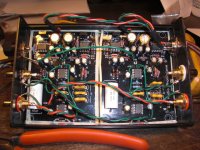
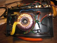
I am not satisfied with the noise/hum that remains. Here's pics of the build as requested by Richard (shameless plug for Ken who supplied the neat/compact 4 pin Mic connectors for power supply)
I will post measurements soon.
Regards, Phil in NJ
Richard and all:
I completed the amp while we were running on a generator and initially it had bad hum on L channel but sounded OK.
Got back to it recently. Found the voltage dividing resistors had a problem-zero drop across R16 and V=+/V- skewed +~3.7V. I tagged meter on board and started looking for a short or whatever & suddenly OK. No amount of flexing/banging/disturbing board or components caused a glitch; left powered up 12 hrs w/Fluke in record mode-no problem/V delta was .3V.
I am not satisfied with the noise/hum that remains. Here's pics of the build as requested by Richard (shameless plug for Ken who supplied the neat/compact 4 pin Mic connectors for power supply)
I will post measurements soon.
Regards, Phil in NJ
Attachments
Last edited:
A word of praise for the VSPS.
G'day all, my two favourite DIY MM phono stages are the ESP P06 and the RJM VSPS. Both phono stages get regular use.
Sadly just today my ESP P06 developed a (regular) fault of losing one channel so I've plugged in my breadboarded VSPS and I don't think I'm losing anything.
One thing about the VSPS that I dearly love is just how 'musical' it sounds, yet I've built other similar one op amp designs that sound.....cold and sterile in comparison. Mr Murdey, you are a genius! Many thanks, Felix.
G'day all, my two favourite DIY MM phono stages are the ESP P06 and the RJM VSPS. Both phono stages get regular use.
Sadly just today my ESP P06 developed a (regular) fault of losing one channel
so I've plugged in my breadboarded VSPS and I don't think I'm losing anything. One thing about the VSPS that I dearly love is just how 'musical' it sounds, yet I've built other similar one op amp designs that sound.....cold and sterile in comparison.
Mr Murdey, you are a genius! Many thanks, Felix.@pfcs49
Sorry for the delay getting back on this. Everything that I can see in the photos looks fine, it's a tidy build, with good cable dressing, all the caps connected in the right orientation etc, so I would not expect a large hum/noise.
Most common cause of undue noise is setting R2 too large for the cartridge used.
The temporary skew of the voltage rails is odd, and would suggest one of the voltage divider resistors might have gone open circuit due to a poor solder joint.
Basically you want to double check all the V+ and V- voltages are hum free and at the expected value of +/- 10-11 V. Then figure out if the hum is 120 Hz or 60 Hz, if in both channels, and if it changes in intensity with the inputs open or connected to the cartridge... and we'll take it from there.
@Felix
Thanks dude. Though despite the name, the P06 is a pretty mediocre baseline to compare to. The VSPS sounds the way it does because it 1) doesn't use an electrolytic on the inverting input and 2) doesn't use film bypass caps, and 3) keeps the regulators on board rather than in the power supply and finally, 4) connects the bypass traces directly at the opamp power pin.
/R
I've got a question about building the power supply for the VSPS 300. I would like to use a transformer a salvaged out of a broken Denon A/V receiver but I'm not sure how to derive the necessary voltages. Two of the secondaries measure 25v. Would I be able to run one of the secondaries into the middle of a full bridge rectifier(1n4007 x4) and get +12.5 off the top and -12.5 off the bottom, or is my thinking off?
No, or rather yes, your thinking is off.
Unless the secondaries have a center tap, you cannot "spit" a single winding into positive and negative voltages as there is no way** for the circuit to reference the zero point.
/R
**I know, you can use a virtual reference, but let's not go there.
Unless the secondaries have a center tap, you cannot "spit" a single winding into positive and negative voltages as there is no way** for the circuit to reference the zero point.
/R
**I know, you can use a virtual reference, but let's not go there.
Last edited:
Or, rather, you could with a rail splitter like the TLE2426 (low current - 20-40 mA) or you might be able to use that with a higher current buffer that would allow more current. There's a good basic discussion of virtual grounding here: Virtual Ground Circuits for those not familiar with it. Not sure if a virtual ground would work in this application, but maybe it's worth some discussion.
On another note, I took the PS for this project (the VSPS, which I'm still breadboarding for now) and used it for my Hagerman Bugle, and it works like a charm! Nice and simple to put together, and WAY outperforms the 9v batteries (a little noisier, but not at the levels I listen).
On another note, I took the PS for this project (the VSPS, which I'm still breadboarding for now) and used it for my Hagerman Bugle, and it works like a charm! Nice and simple to put together, and WAY outperforms the 9v batteries (a little noisier, but not at the levels I listen).
Well it does have two 25v secondaries. Would the Xreg be able to handle the higher voltage, assuming that I use higher voltage rated capacitors on C4 and C5? I see that the OPA27G can handle 44V, are there any disadvantages of running close to that limit?
Then what about an inverting supply? Akin to: Simple 555 Switching Circuit Provides Negative Supply from Single Positive Supply | Circuit Diagram. You'd need to flesh it out a bit.
There are lots of web resources for inverting supplies, but I've only worked with the rail splitter so can't vouch for noise or current capacity, etc. Maybe there's something out there that can work.
There are lots of web resources for inverting supplies, but I've only worked with the rail splitter so can't vouch for noise or current capacity, etc. Maybe there's something out there that can work.
Ok, so it looks like we went there... 😀
@Carlp
Here's the thing: $25 gets you a nice 2x12V toroid and you hook it up and it works. That vs. using the wrong transformer, jerry-rigged to do the job by any of the methods you sketched out above all of which require extra circuitry, and extra time and effort putting it together and testing ... hand here's the kicker: none of which are going to do as good a job sonically as a simple split/dual secondary.
Virtual grounds are for when you want to power a circuit from a single battery. "Simple" switching power supplies should not be allowed to come within 10 meters of an audio system. 🙂
@Shepdog
Nope. You'd pop the op amps. The X-reg ICs (IC3,4) are powered by the full unregulated input voltage, which is expected to be about ~80 V from V++ to V--.
Last edited:
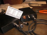
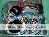
Cheap, shielded, fast delivery and best of all, Richard can help you troubleshoot if things go ary. $17 each.I've finished my power supply. My first project of this type. I've used 50VA Amtek transformers at $17 each. The IEC connector incorporates a fuse and lighted switch to simplify my hole drilling and wiring. I have the IEC on what I plan to be the side for access. The umbilicals (or is that umbilici) exit the back. Comments and suggestions welcome.
Dave
BYW, how do you get the pictures to enlarge. The little thumbnalis just move a bit when you click on them?


Yep, understood rjm and Wintermute. Oh, and somehow I didn't see your comment about "let's not go there" until your reply below...sorry! I come at this from the standpoint of die-hard frugality, hence I take old equipment from friends, pillage useful parts to fuel my obsess...er...habit, then do my best to build GOOD equipment from them. And I've had remarkable success with the help of DIYAudio and other fora like this.
But, of course, cheap switching supplies probably DON'T belong anywhere near audio equipment.
 That said, the question was about using existing parts, so I thought I'd answer that way. And as I posted above, I used a rusty old filament iron and whatever diodes and caps I had lying around to make up the basic PS for VSPS and it's remarkably silent. The only noise I'm getting using it for my Bugle is the hiss I get from the OPA2137s I'm using in the gain positions for that amp. That hiss existed running off 9v batteries too.
But, of course, cheap switching supplies probably DON'T belong anywhere near audio equipment.
That said, the question was about using existing parts, so I thought I'd answer that way. And as I posted above, I used a rusty old filament iron and whatever diodes and caps I had lying around to make up the basic PS for VSPS and it's remarkably silent. The only noise I'm getting using it for my Bugle is the hiss I get from the OPA2137s I'm using in the gain positions for that amp. That hiss existed running off 9v batteries too.Well its settled, I've purchased a 1,200 watt gas powered generator. But really, thanks to both of you for your help.
Richard and all:
I completed the amp while we were running on a generator and initially it had bad hum on L channel but sounded OK.
Got back to it recently. Found the voltage dividing resistors had a problem-zero drop across R16 and V=+/V- skewed +~3.7V. I tagged meter on board and started looking for a short or whatever & suddenly OK. No amount of flexing/banging/disturbing board or components caused a glitch; left powered up 12 hrs w/Fluke in record mode-no problem/V delta was .3V.
I am not satisfied with the noise/hum that remains. Here's pics of the build as requested by Richard (shameless plug for Ken who supplied the neat/compact 4 pin Mic connectors for power supply)
I will post measurements soon.
Regards, Phil in NJ
I finally got back to the clone. I had made R2 96ohms to get ~42dB gain w/.8mV med output Benz, hoping to level match my B&O carts thru the Yamaha C2-x control amp. The background noise level was pretty bad, and the level was too low.
So I removed R1s and R2s and soldered in sections of IC sockets as suggested by SpecialIdiot (sectioned the plastic across 5 pins, pushed the middle 3 up and out of the frame, leaving it more rigid) and raised R2 to 300ohms.
The hum and noise remained the same, but the S/N got much better and acceptable to me.
I see Richard's admonition to avoid values below 500ohms for R2-maybe this is why?
- Home
- Source & Line
- Analogue Source
- The Phonoclone and VSPS PCB Help Desk