R1/R2 will be nominally chosen for the Dl-103, but should give good results with a wide range of cartridges and systems.
You can contact me about this by email, rjm003.geo at yahoo.com.
/R
You can contact me about this by email, rjm003.geo at yahoo.com.
/R
By the way, a great place to get mica caps for the RIAA section is westfloridacomponents ebay store...
http://myworld.ebay.com/westfloridacomponents/
(I typically went with C1= 1000pF, C2= 2800pF + 120pF, unfortunately while he has plenty of 2200pF there are no 680 pF complement offered...)
he also has some good prices on bridge rectifiers...
Also, today I'm going to buy a bk precision 810C capacitance meter. I've been meaning to get something better than my Fluke 83 for some time. This means that the RIAA components shipping with the Special Edition Phonoclone RC will be fully matched to 0.5% accuracy!
/Richard
RC limited Kit : Update and Details
Time for a status report. All parts except for the board themselves and the ZA caps have been ordered. The OP27s are backordered from Digikey until Sept 20th, but since Olimex wont be open until Sept 3rd, everything is still on track for Oct 1 ship date.
Here is the detailed parts list:
Part // Description // Quantity Supplied
U1,U2 Analog Devices OP27GP 4
(socket) 8 pin gold-plated DIP socket 4
LM7810 +10 V positive fixed voltage regulator 2
LM7910 -10 V positive fixed voltage regulator 2
C1 1000 pF Cornell Dubilier mica capacitor (matched) 2
C2a 2200 / 2800 pF Cornell Dubilier mica capacitor (matched)* 2
C2b 680 / 120 pF Cornell Dubilier mica capacitor (matched)* 2
C3 4.7 uF 50 V Black Gate N non-polar electrolytic capacitor 2
C4,5 1000 uF 25 V Nichicon FW (audio) electrolytic capacitor 4
C6,7 100 uF 25 V Nichicon FW (audio) electrolytic capacitor 4
C8-11 100 uF 35 V Rubycon ZA ultra low impedance electrolytic capacitor 8
R1 30 ohm 1/4W Riken Ohm precision carbon film resistor 2
R2 1 kohm 1/4W Riken Ohm precision carbon film resistor 2
R3,R4 2.2 kohm 1/4W Takman carbon film resistor 4
R5 110 kohm 1/4W Takman carbon film resistor (matched) 2
R6 750 kohm 1/4W Takman carbon film resistor (matched) 2
R7 33 kohm 1/4W Takman carbon film resistor 2
R8 47 ohm 1/4W Allen Bradley carbon composition resistor 2
R9-12 5.1 ohm 1/4W Allen Bradley carbon composition resistor 8
Yes, there are still plenty of kits left!
Richard
Attachments
Power supply question
Hi there!
I have now built the phonoclone and I am putting together the power supply, and I just want to clarify something.
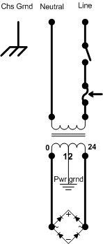
I have a power transformer with 24v out, tapped at 12v, so there are three leads - 0, 12v, 24v.
Do I connect the 0v and 24v secondary to the AC input of the rectifier and output it like so:
- out on Rectifier = -12v rail on Phonoclone PCB
+ out on Rectifier = +12v rail on Phonoclone PCB
12v (CT) tap from transformer = 0v rail on Phonoclone PCB
Is that the correct way to do it?
The reason why I am confused is that I also got another design printed from somewhere on the website that requested 2x12v secondaries, putting both through an arrangement of 2 bridge rectifiers (the instructions call it a "Gainclone-style power supply"). Am I correct in saying that because my power transformer is 24v center tapped, I do not need to do this?
I hope you can understand what I mean!
Thanks
Kaban.
Hi there!
I have now built the phonoclone and I am putting together the power supply, and I just want to clarify something.
I have a power transformer with 24v out, tapped at 12v, so there are three leads - 0, 12v, 24v.
Do I connect the 0v and 24v secondary to the AC input of the rectifier and output it like so:
- out on Rectifier = -12v rail on Phonoclone PCB
+ out on Rectifier = +12v rail on Phonoclone PCB
12v (CT) tap from transformer = 0v rail on Phonoclone PCB
Is that the correct way to do it?
The reason why I am confused is that I also got another design printed from somewhere on the website that requested 2x12v secondaries, putting both through an arrangement of 2 bridge rectifiers (the instructions call it a "Gainclone-style power supply"). Am I correct in saying that because my power transformer is 24v center tapped, I do not need to do this?
I hope you can understand what I mean!
Thanks
Kaban.
Eh, no expert here. but I think so.
Its easy to check though. Wire it up that way and check with a DMM before connecting it to the phonoclone. Neg lead on the CT, and you should see the + and - 12V on the 2 rectifier outputs.
Have you seen the construction guide on the phonoclone page or RJMs site?
Fran
Its easy to check though. Wire it up that way and check with a DMM before connecting it to the phonoclone. Neg lead on the CT, and you should see the + and - 12V on the 2 rectifier outputs.
Have you seen the construction guide on the phonoclone page or RJMs site?
Fran
OK!
Now I have done that, I am not getting any reading at all in volts across the + - of the rectifier in DC. To double check I desoldered the 24v AC lead and tested for AC across the secondary coil with no results.
Could it be I fried the transformer? I dont really know how easy it is to do, but I did arrange two rectifiers on the secondary coil probably in an incorrect manner (as per the "gainclone" PS instructions). Maybe that did it? Hmm.
Oh you can do it easy enough alright!!!!!
Just to double check - make sure you have mains voltage at the Tx primaries (ie that a fuse isn't gone). If you then don't have anything on the secondaries, well someting in there is fried.
on a brighter note, if its a toroidal, then the wires make nice internal wiring for an amp or something (although the varnish is a pain to deal with)
Fran
As silly as it seems, make sure your reading DC after the bridge rect. and AC before..
Did you have a fuse or switch in line? Loose wire, cold solder joint on the AC supply side?
Did you have a fuse or switch in line? Loose wire, cold solder joint on the AC supply side?
Hi,
was the transformer miswired at some time when connected to the mains?
The fusible link inside may be blown due to over temperature.
Check for continuity in each of the windings.
was the transformer miswired at some time when connected to the mains?
The fusible link inside may be blown due to over temperature.
Check for continuity in each of the windings.
Re: Power supply question
the dual rectifier can only be fitted to a dual secondary transformer.
The single rectifier can be fitted to either a centre tapped or dual secondary.
One can convert a dual secondary to centre tapped.
One cannot (easily) convert a centre tapped to dual secondary.
Hi,kaban said:Hi there!
I have now built the phonoclone and I am putting together the power supply, and I just want to clarify something.
I have a power transformer with 24v out, tapped at 12v, so there are three leads - 0, 12v, 24v.
Do I connect the 0v and 24v secondary to the AC input of the rectifier and output it like so:
- out on Rectifier = -12v rail on Phonoclone PCB
+ out on Rectifier = +12v rail on Phonoclone PCB
12v (CT) tap from transformer = 0v rail on Phonoclone PCB
Is that the correct way to do it?
The reason why I am confused is that I also got another design printed from somewhere on the website that requested 2x12v secondaries, putting both through an arrangement of 2 bridge rectifiers (the instructions call it a "Gainclone-style power supply"). Am I correct in saying that because my power transformer is 24v center tapped, I do not need to do this?
I hope you can understand what I mean!
Thanks
Kaban.
the dual rectifier can only be fitted to a dual secondary transformer.
The single rectifier can be fitted to either a centre tapped or dual secondary.
One can convert a dual secondary to centre tapped.
One cannot (easily) convert a centre tapped to dual secondary.
AndrewT - I haven;t posted yet because theres still one or 2 things to try out so I want to look at those yet.....
Fran
Fran
Do I connect the 0v and 24v secondary to the AC input of the rectifier and output it like so:
- out on Rectifier = -12v rail on Phonoclone PCB
+ out on Rectifier = +12v rail on Phonoclone PCB
12v (CT) tap from transformer = 0v rail on Phonoclone PCB
Is that the correct way to do it?
In a word; yes. The diagram Troy uploaded is also correct and clearly shows how to do it.
Just to recap the various replies:
If you have a center tapped single secondary output winding, 0-12-24V then the only option is a single full-wave bridge rectifier.
If you have two independent secondaries, 0-12 V and 0-12 V, you have the option of using two full-wave bridge rectifiers, but you can tie the windings together in series and use one bridge if you want.
The power supply diagram used to show the two-bridge version, but I recently simplified it to show a single bridge connection. I see now that I didn't include the bridge labels (~~+-) on the new diagram. I will fix that ...
Measuring transformer output voltages is a bit tricky with the supply disconnected from the circuit, since there is no load and no filter capacitors present. The most reliable check is to measure AC voltages, both at the primary and secondary (before the rectifier) windings.
/R
hello Richard
i am searching for a 12 volt transformer to feed the Phono kit
and can order them from plitron no problem
But i have also a transformer in my hobby box
that one is 2x 16volt 4 Ah is this also usefull without degrading the sound quality of the phono kit?
i am searching for a 12 volt transformer to feed the Phono kit
and can order them from plitron no problem
But i have also a transformer in my hobby box
that one is 2x 16volt 4 Ah is this also usefull without degrading the sound quality of the phono kit?
As far as the kit goes, please use a 12V transformer as the filter capacitors are only rated to 25V and the DC rails from 16 VAC are too close to that.
Generally, regarding sound quality, I found it is best to keep the differential voltage accross the regulator (Vin-Vout) less than 10V. 5-7V appears ideal.
If you are ordering from plitron, ask for electrostatic screen and magnetic shield... tell them the VA isnt critical, and you'd be happy to get a previously designed model, anything with 2x12VAC outputs/screen/shield.
(otherwise you cant get the screen option etc under a 5pc min order)
That's how I got mine, which are 160 VA. Realistically 60-80 VA, if they have it already designed, should be more than enough.
Since you are in Europe, you may find it cheaper to get custom toroidal transformers made closer to home. Just saying...
/R
- Home
- Source & Line
- Analogue Source
- The Phonoclone and VSPS PCB Help Desk