Funny you should mention the connection to GND. I have, for the first time in a very long time, a small amount of hum in my phonoclone. It's been such a long time that I may have forgotten what I learnt.
Anyhow, there is some hum, of the level that is just audible at normal volume with no music playing. It's 120 Hz ripple as near as I can tell.
There's 2-3 possibilities, I'll run through them in the next few days. First on the list though is the position of the GND pad between IN- and OUT-. With a shared power supply as I use here this may not be the ideal place for that. Fortunately one of the COM on the other side of the board is unused, so I will switch over to using that for the chassis connection. (originally the ground wire was only the short yellow-green section and connected to the COM at the XLR panel jack, it moved to the board GND when I added that feature several revisions of phonoclone 3 ago.)
More in a bit.
It plays music just fine. Won't comment on the sound though since it's only a few hours old, and anyway need to tackle the hum first.
Last edited:
I noticed that you keep using 3x1nF caps for RIAA. If it is just a practical issue, Mouser these days has quite cheap 3nF mica caps.
I remember reading I think in Douglas Self's book that paralleling caps reduces noise, so there could be some merit in continuing to use 3x1nF caps though.
I remember reading I think in Douglas Self's book that paralleling caps reduces noise, so there could be some merit in continuing to use 3x1nF caps though.
It's a cost issue, buying one (very) large bag of 1 nF mica caps is way cheaper than smaller quantities of two different parts. It's also more convenient for stock-keeping.
(You are right though, in single unit prices it is probably cheaper to use 3nF. Of course the boards permit this, or any combination of up to three caps for C2.)
(You are right though, in single unit prices it is probably cheaper to use 3nF. Of course the boards permit this, or any combination of up to three caps for C2.)
Quick report on the 4.0b hum issue:
I fixed it, but it required a fair bit of surgery on the grounding layout to get there. While it is no longer audible at normal volume levels the noise is present in measurements whereas the phonoclone3 had none. So there is still work to be done, and to be honest I don't have a 100% understanding of exactly what is going on. Yes the grounding connection is slightly less rigorous than the 3.5h boards - I made more use of the ground plane rather than separate connections - but I don't understand why such large noise currents are flowing though that particular small section of ground plane that a small ground loop into the output signal section should cause such a large amount of interference.
I'll have more to say in a bit, but if you read this and signed up for the 4.0b evaluation boards please come talk to me before you start building.
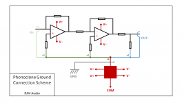
FYI this is how I have it connected up now, and how the phonoclone 3 is also wired. With the 4.0 boards as received, nodes n1~n5 were grouped into a small cluster and connected directly to the ground plane instead daisy-chained one to each other in order.
To my way of thinking the only point up for discussion is the connection n5 to the chassis GND. According to most textbooks it should be close to n1 instead, while in the phonoclone3 is was closer to COM.
/R
To my way of thinking the only point up for discussion is the connection n5 to the chassis GND. According to most textbooks it should be close to n1 instead, while in the phonoclone3 is was closer to COM.
/R
Attachments
I think the loop areas may be your PCB problem.
Looking at n1 and the loop area to it's left.
That input loop area can be made very small by bringing the TWO WIRE input to the opamp as a twisted pair that becomes a pair of overlaid traces.
If instead you take n1 to some remote location you have INCREASED the loop area because you have SEPARATED the two wires of the input connection.
Move onto n2. Again the loop area of the two wire connection to it's left must be minimised. taking n2 to some remote location INCREASES loop area.
You must think through each two wire connection and minimise the loop area.
If that were true ... I'd I'm not suggesting it isn't, I'm just trying to think things through here ... if that were true wouldn't the original design where the IN- signal dropped directly into a ground plane which covered the IN+ trace right up to the op amp input have worked nicely, since it had minimal loop area?
Instead I'm getting a better result with all the ground traces pulled out of the ground plane, connected back into it at a single point.
I mean I think you are basically on to something here: the residual problem seems to be over-air pickup into the input from the power supply, and therefore relates to shielding, length, placement, and loop area of the input wires and input traces... I'm just at a loss to explain why it's such a mess this time around where the Phonoclone 3 worked nicely in the same case etc. with no great concern for loop area etc.
So where we are currently:
Output noise is about 2.5 mV p-p in one channel, 4 mV p-p in the other. The larger noise is associated with the board furthest away from the I/O, with longer internal connecting wires. The noise is 120 Hz fundamental, with a triangular shape characteristic of the shunt/charging currents flowing through most sections of the S-Reg circuit. (confirmed via LTSpice.)
The V+ and V- voltages are noise free. Galling as it is to admit, the power rails of the phonoclone 4 have less noise on them than the output, I kid you not. In itself the S-Reg works just fine.
Changing the gain of the phonoclone changes the output noise in proportion. No surprise there, but it proves that the noise pickup is in the input stage.
All my tinkering about with the ground layout and connections has not made a great difference, to be honest, though I would say it's a definite improvement the order is about 2~3x rather than order of magnitude level.
So my operating theory is that while the input section is a nice little receiver, the main problem is the S-Reg I've put together is an unusually nice little noise generator. Why that might be is what I will be looking at next.
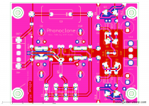
From what I can see the placement of R9,10 are less than ideal. The should be the other side of the transistors next to R11,12. Nothing else jumps out. (R9,10 were moved from their original position to ease crowding near the main filter cap, and later mods removed the direct return path of the ground plane. When I moved them I was no longer thinking about why I had put them where I did in the first place. Happens...)
Output noise is about 2.5 mV p-p in one channel, 4 mV p-p in the other. The larger noise is associated with the board furthest away from the I/O, with longer internal connecting wires. The noise is 120 Hz fundamental, with a triangular shape characteristic of the shunt/charging currents flowing through most sections of the S-Reg circuit. (confirmed via LTSpice.)
The V+ and V- voltages are noise free. Galling as it is to admit, the power rails of the phonoclone 4 have less noise on them than the output, I kid you not. In itself the S-Reg works just fine.
Changing the gain of the phonoclone changes the output noise in proportion. No surprise there, but it proves that the noise pickup is in the input stage.
All my tinkering about with the ground layout and connections has not made a great difference, to be honest, though I would say it's a definite improvement the order is about 2~3x rather than order of magnitude level.
So my operating theory is that while the input section is a nice little receiver, the main problem is the S-Reg I've put together is an unusually nice little noise generator. Why that might be is what I will be looking at next.
From what I can see the placement of R9,10 are less than ideal. The should be the other side of the transistors next to R11,12. Nothing else jumps out. (R9,10 were moved from their original position to ease crowding near the main filter cap, and later mods removed the direct return path of the ground plane. When I moved them I was no longer thinking about why I had put them where I did in the first place. Happens...)
Attachments
Last edited:
No I haven't. Why do you think it would be a good idea to bring the returns back to the noisy side of the regulator?
I was thinking connecting everything to 0 on a pure star ground to eliminate the possibility of issues with the ground plane connections and holes.
Perhaps on the regulated 0 then.
I also feel a bit weird that the input and output return currents move on the same path on the ground plane (mixing high-low current and voltage returns).
Perhaps on the regulated 0 then.
I also feel a bit weird that the input and output return currents move on the same path on the ground plane (mixing high-low current and voltage returns).
The boards have much less noise sitting on the bench with a 47 ohm resistor across the inputs than they do in the case wired up with a 47 ohm dummy load over the RCA jacks.
I tried moving R9,10 to take the returns directly to the filter caps, but it made no difference.
It's all to do with the chassis.
If the chassis connection is taken at COM where it connects to the XLR jack, the noise is huge. If the connection is made at IN- at the RCA jacks it is lower but still more than when the connection is made at or near n4.
Moving the input and output wires around does not change anything.
In short it behaves more-or-less like I would expect on the assumption of massive amounts of noise currents generated by the voltage regulation section and coupled into the chassis and then back into the board's input stages. I just don't understand why it's become such an issue with these new boards when it wasn't before.
Progress.
Removed the input wires, replaced with a dummy 47 ohm resistor connected at the board input. Ripple noise drops by half, almost invisible in the broadband noise now.
RMS value of the output noise is 0.4 - 0.5 mV, the outer board still being very slight more noisy. Just twisting the dummy load 90 degrees changes the amount of output noise slightly. The position of the chassis ground connection no longer has a big influence. As configured I calculate the broadband noise from the op amps should total about 0.3 mV. So we are really close now to being home free.
Of course I don't have the boards connected to the input RCA anymore, so that's a problem... but after working though a couple of dozen mods and changes the boards are pretty much wrecked anyway. So what I want to do is strip the case and start over from scratch using shielded wiring and fastidious construction.
For those of you with boards ... as far as I can tell the boards as shipped are not flawed. None of my mods that supposedly "improved" on the grounding layout did anything substantial, only removing the input wires drastically changed the situation. I suggest giving it a shot and see how it goes.
Hi Richard, I have assembled and used the VSPSX board you sent me. It sounds good but I too have a ground loop issue. I am going to chase and troubleshoot that issue tonight.
An externally hosted image should be here but it was not working when we last tested it.
With the VSPS(X) you want to measure and test with the inputs shorted.
Your build looks nice and neat, my only concern is having the power transformer and related components so close to the input connections. Also with this kind of high feedback noninverting circuit you want to keep the input wires as far away from the output wires as possible.
So far as low-level pickup is concered the VSPS isn't remotely as troublesome as the phonoclone, but it is true that the VSPSX and PC4 share the same S-Reg voltage regulator so that is at this stage a point of concern.
Please keep us updated.
Last edited:
yeah, I'm messing with toroid shielding now. I just changed all of the com and ground wires to eliminate loops. the him isn't noticible while music is playing, but it's there when the music is paused. nothing has made a change as of yet, shielding or changing common wires around. touching an input wire sure gives me a ton of feedback output though. I'll keep tinkering or I'll just live with it.
interesting that using earth ground to the case makes it much noisier. so I measure the difference between common and Earth, it's 35VAC. so I'm not using that.
interesting that using earth ground to the case makes it much noisier. so I measure the difference between common and Earth, it's 35VAC. so I'm not using that.
yeah, I'm messing with toroid shielding now. I just changed all of the com and ground wires to eliminate loops. the him isn't noticible while music is playing, but it's there when the music is paused. nothing has made a change as of yet, shielding or changing common wires around. touching an input wire sure gives me a ton of feedback output though. I'll keep tinkering or I'll just live with it.
interesting that using earth ground to the case makes it much noisier. so I measure the difference between common and Earth, it's 35VAC. so I'm not using that.
Wait, when the pcb ground is DISCONNECTED from the case you have 35v between the pcb ground and the mains earth? That would surely explain the hum when the pcb ground is connected to the case (assuming your mains ground is connected to the chassis for safety). I suspect it would explain the rest of the hum even when disconnected too.
But why would that happen? The only time I've seen that was when there was an inadvertent connection between a power rail and the standoffs to the chassis. In my case a washer was too big and I hadn't noticed the connection. Since it was 35v and I hadn't touched the case yet, it wasn't obvious at first. I noticed when I tried running a ground between my amp (in this case, the offending component) and a preamp.
Can you clarify if that's what you mean?
right now, there is no earth ground at all. The circuit common is grounded to the chassis. There is no connection anywhere else. The power rails are all well away from touching any part of the case, which is also anodized anyway. I was surprised when I measured that.
But currently, I am NOT using an earth ground at all. Just a single point chassis ground. I attached another wire to that and touched it to various other ground points and it made no change. Like Richard said, it may be EMI from the transformer, however, encasing it and making a steel divider didnt help either. I guess the next experiment is to remove T1 and the diode bridges to their own enclosure and see what happens.
Been sidetracked with several projects tonight, I will work on it more later. ;-) thanks for the input guys
The earth connection to circuit common is usually made downstream at the amplifier, making the connection at the phono stage as well would be very likely to cause ground loops. So it doesn't surprise me too much that you find it hums less with the earth disconnected.
If my understanding is correct though, there should not be 35 V between chassis and earth in either case once the phono stage is connected to an earthed amplifier. It might float up to that level when disconnected, but in that situation it would hum less when earthed, not more. It does seem like there is some significant leakage going on, I just can't see clearly what's causing what.
Your situation, where most changes do not influence the noise level especially, is very much what I have been facing recently with the PC4. It's also similar in output magnitude despite the very different circuit gain. Anyway - I feel your pain! I also really, really, really want to see this problem cracked.
Last edited:
..........I have assembled and used the VSPSX board ..............I too have a ground loop issue. I am going to chase and troubleshoot that issue tonight.....................interesting that using earth ground to the case makes it much noisier. so I measure the difference between common and Earth, it's 35VAC. so I'm not using that.
.................. I measure the difference between common and Earth, it's 35VAC. so I'm not using that.
If I am reading this correctly you have built a Mains powered pre without a Safety Earth.right now, there is no earth ground at all. The circuit common is grounded to the chassis. There is no connection anywhere else. ...............But currently, I am NOT using an earth ground at all. Just a single point chassis ground. ................
You have measured 35Vac between Main Audio Ground and Chassis
When you connect another piece of equipment via an interconnect to that faulty VSPSX, the 35Vac must send some current along that link.
Can't you see that making the connection is allowing interference current to flow between your pieces of equipment?
1.) you must install a Safety Earth in your mains powered equipment.
2.) you must prove to yourself that you do not have 35Vac on the interconnect BEFORE you connect it to any other equipment.
Last edited:
- Home
- Source & Line
- Analogue Source
- The Phonoclone and VSPS PCB Help Desk