Phonoclone 4.0b (upgrade)
Out of self-interest the first batch will be compatible with the old 3.5"x2.5" hole spacing. I will be upgrading my own build and prefer not to have to drill more holes in the case.
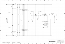
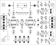
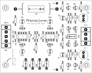
Final design shown below.
There will be nine sets available, lead time 2-3 weeks. If you want to upgrade (all previous versions) -> 4 drop me a pm.
Out of self-interest the first batch will be compatible with the old 3.5"x2.5" hole spacing. I will be upgrading my own build and prefer not to have to drill more holes in the case.
Final design shown below.
There will be nine sets available, lead time 2-3 weeks. If you want to upgrade (all previous versions) -> 4 drop me a pm.
Attachments
Last edited:
How about 2 sets of holes for a couple of versions? It would be ugly. Maybe some slots
About trimmers I do not mind them, but an option to replace it with a resistor might be nice. The components can be on top of the each other to save space
And I really hate dip switches and standoffs
About trimmers I do not mind them, but an option to replace it with a resistor might be nice. The components can be on top of the each other to save space
And I really hate dip switches and standoffs
Last edited:
Protection diodes sound a great and sensible idea.
Personally I like the idea of having R1 and R2 as 'plug in' to enable easy swapping of values (I use PCB header strips for that purpose)
The idea of standardising the mounting holes is a good one, but if its possible having two sets of mounting holed on one board would (assuming its possible) be better
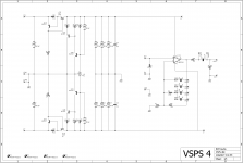
The resistors + option trim are easy to do and work naturally since combining resistors in series with the trim pot reduces the adjustment sensitivity.
41a attached shows R19,20 added, trim renames to R21. If you don't want to use the trim just short between R19-20 across the line indicated.
In this iteration, R19,20 would be 475 ohms, while the trim pot would be 100 ohms or thereabouts.
41a attached shows R19,20 added, trim renames to R21. If you don't want to use the trim just short between R19-20 across the line indicated.
In this iteration, R19,20 would be 475 ohms, while the trim pot would be 100 ohms or thereabouts.
Attachments
Blog post repository for the latest Phonoclone 4 materials.
http://www.diyaudio.com/forums/blogs/rjm/1411-phonoclone-4.html
http://www.diyaudio.com/forums/blogs/rjm/1411-phonoclone-4.html
Richard, the regulator circuit can be adapted to VSPS 300 ?.
What advantages would it bring? What input voltage and output voltage? Greetings.
What advantages would it bring? What input voltage and output voltage? Greetings.
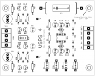
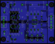
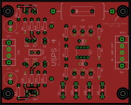
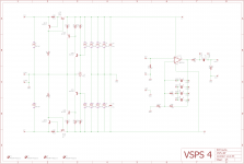
VSPS 4
We can give the VSPS the same treatment as the Phonoclone, revising it up to "4" status with the new layout and S-Reg. Both boards are actually derived from the VSPSX linked to in the previous post.
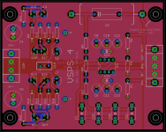
I really like the VSPS 4 layout. The symmetry is pleasing and the ground layout works out perfectly, all while the phono stage circuit never breaks to the top trace and keeping the I/O in the standard place.
The plan is to manufacture the VSPS 4 boards once the Phonoclone 4 has been tested.
We can give the VSPS the same treatment as the Phonoclone, revising it up to "4" status with the new layout and S-Reg. Both boards are actually derived from the VSPSX linked to in the previous post.
I really like the VSPS 4 layout. The symmetry is pleasing and the ground layout works out perfectly, all while the phono stage circuit never breaks to the top trace and keeping the I/O in the standard place.
The plan is to manufacture the VSPS 4 boards once the Phonoclone 4 has been tested.
Attachments

Last edited:
Have you looked at the current routes to return the currents to their sources?the ground layout works out perfectly,

Richard, I can not do my DIY job.
Tell me what performance advantages this VSPS 4 has with what I own is the VSPS 300.
Greetings.
Tell me what performance advantages this VSPS 4 has with what I own is the VSPS 300.
Greetings.
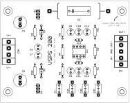
VSPS 200
How much difference does the voltage regulator make to the sound quality?
That's a tricky question, because with op amp ICs at least a poorly performing regulator should work as well as a super high performance regulator. The op amp's PSRR is so high the residual noise on the regulator output is all cleaned up below the level of the op amp's output self-noise either way. There are other considerations of course, like output impedance, and maybe a high performance regulator sounds worse, if there is overshoot or instability, but from a numbers viewpoint, the simple Zener reference / pass transistor shown in the VSPS 200 below is sufficient. Everything above that is complexity for complexities sake.
I like working on a layout with plenty of room on the board. "Minimalist luxury". You can spread out and enjoy yourself.
Attachments

Last edited:
@alpuy
I hope the post above answers your question. The "4" and 200 is a reworking, the layout is refined compared to the 300 and the regulator substituted. Which regulator you want - Z, X, S or something else entirely - is really a matter of which approach (simple, high performance, shunt, ???) you personally find more appealing.
I hope the post above answers your question. The "4" and 200 is a reworking, the layout is refined compared to the 300 and the regulator substituted. Which regulator you want - Z, X, S or something else entirely - is really a matter of which approach (simple, high performance, shunt, ???) you personally find more appealing.
That was the intention, yes. Did I miss anything?
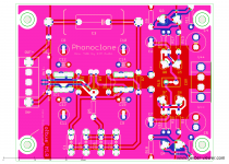
I can now see that the top plane has very few slots/cuts in it.This is what I was talking about for at any rate: all the components connect to the ground plane in the natural order without inconveniencing the traces or component placement.
As long as no component/trace crosses over a slot, then the plane is capable of allowing the current to find the lowest impedance route back to source.
What about the trace from R15 to Q20 and from R16 to Q19?
The pic you first showed in post3529 is riddled with slots/cuts/gaps that could never be an effective plane.
Last edited:
Andrew,
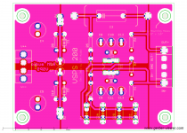
That's an x-ray view showing you both the top and bottom traces simultaneously. Not the easiest to visualize, I admit.
That's an x-ray view showing you both the top and bottom traces simultaneously. Not the easiest to visualize, I admit.
Am I reading post3532 correctly in that I see a trace from R15 to Q20 passing across a slot in a plane?
Does that trace carry a current?
What route does the return current take to get back to source?
Does that trace carry a current?
What route does the return current take to get back to source?
I'm not confident I can answer that accurately, so instead let me show you the top and bottom traces of the latest version 4.0f (layout essentially unchanged from 3532 etc.)
Attachments
- Home
- Source & Line
- Analogue Source
- The Phonoclone and VSPS PCB Help Desk