Trying to gathering up the parts for a build. Can C3 (10uf 50V) on the phono board use 35V caps?
The challenge is the 1k69 resistor. Caddock standard is 1k62. Only one I could find with that value is Holco.
Did not think it too critical, but Percy is away until mid-Oct and wanted something to put in the circuit. Will order from him when he is back.
Ideal value is 1596R - instead of 1k62.
You cannot change it to other value because you change RIAA.
K
You cannot change it to other value because you change RIAA.
K
Hi Peter,
The phono project looks great!
Would this phono amp also be able to handle MC cartridges directly?
Also your board accomodates the Hammond transformer. Could I buy this one from you as well? (would save a lot in transport costs)
Thanks...
The phono project looks great!
Would this phono amp also be able to handle MC cartridges directly?
Also your board accomodates the Hammond transformer. Could I buy this one from you as well? (would save a lot in transport costs)
Thanks...
This circuit is designed to handle MC cartridges directly. I've been using it with Shelter 901 and did a lot of tests with ZYX Universe.
Also your board accomodates the Hammond transformer. Could I buy this one from you as well? (would save a lot in transport costs)
I can also supply transformer, but airmail shipping to EU would cost you additional $20
Attenuator value
Peter,
I'm interested in building one of your phono stages and it will be driving a passive attenuator. What input impedence would you recommend? The attenuator output will be driving an active x-over which was designed for 10K impedence. I'm wondering if I'll need a buffer.
Thanks in advance.
Peter,
I'm interested in building one of your phono stages and it will be driving a passive attenuator. What input impedence would you recommend? The attenuator output will be driving an active x-over which was designed for 10K impedence. I'm wondering if I'll need a buffer.
Thanks in advance.
Hi Peter, I built the phono amp yesterday and can't get any sound out of it. I am getting +/- 15V from the regulator so I am assuming it is OK. Can you help me debug by providing some measuring points?
I think I connected it correctly, I jumpered the 4 places where marked. What are they R marking on the caps on the board for? I soldered the caps to the R point and to the other side, is that correct?
Anything else you can think of would be appreciated. Thanks!
I think I connected it correctly, I jumpered the 4 places where marked. What are they R marking on the caps on the board for? I soldered the caps to the R point and to the other side, is that correct?
Anything else you can think of would be appreciated. Thanks!
There are 4 jumpers from PS to phono stage and another 4 jumpers on phono board itself. Check if you have -15V on pin 4 and +15V on pin 7 on all chips.
If R7 isn't installed, the output is taken directly from C2 pin.
What DC offset are you reading?
The R indicates red lead on a V-Cap.
If R7 isn't installed, the output is taken directly from C2 pin.
What DC offset are you reading?
The R indicates red lead on a V-Cap.
Jumpers
I'm (slowly) in the process of building this preamp as well. Regarding the jumpers on the phono board (not the jumpers from the power supply section), note that there are 2 silkscreen lines indicating where the jumpers go on the top of the board, and the other two silkscreen lines are on the bottom of the board. You'll note in Peter's photos, however, that he has all 4 jumpers on the bottom (not that it matters).
Mike
PS I'm now working on the heatsinks...
I am using an original Kondo Audionote (Japan) Io cartridge which has a very low outputm - around 0.05mv and an impedance of about 2 ohms. It needs a lot of help! Can any configuration of this amp handle this small a signal reasonably well?
Many thanks.
Many thanks.
Last edited:
You would need a version with 90dB of gain. This is possible with this circuit, although I never tried it.
I'm starting building another unit with which I will experiment more.
I'm starting building another unit with which I will experiment more.
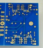
Here, how the jumpers should be installed on phono board. Make sure they are clear the traces underneath. If you prefer to mount them in a top layer, it's fine too, although they might interfere with the caps.
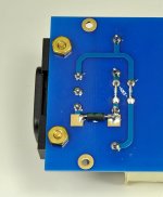
For this board, I'm starting with the transformer, as I want to measure all voltages step by step. So, the 48VA Hammond 229D24 (rated 2x 12V AC) produce actually 15.4V AC (my mains are 124V today), which is quite suitable for the planned 15V regulator output.
Please note the pcb mount fuse and 2 jumpers which set transformer's primary for 115V. For 230V mains only one jumper need to be installed.
Attachments
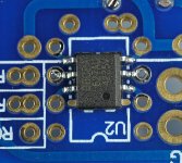
You can use both DIL and SMD op amp packages. With SMD, some pins need to be trimmed so they not interfere with pads nearby.
First picture shows op amps in PS section: top left pin is cut off completely and top right slightly trimmed.
Second picture shows opamp in phono section, here both bottom pins are cut off.
First picture shows op amps in PS section: top left pin is cut off completely and top right slightly trimmed.
Second picture shows opamp in phono section, here both bottom pins are cut off.
Attachments

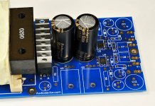
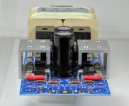
I next install rectifiers and main filter caps. MUR860 is my preferred diode but of course other types can be tested here as well and to make things easier I marked pads with K and A. BG STD 1000/25 work very well as main filter caps in a phono circuit (better than any other BGs). Alternately, Panasonic FC or Elna Silmics could be also considered.
I'm getting approx 19V DC after smoothing and under full load.
I'm getting approx 19V DC after smoothing and under full load.
Attachments
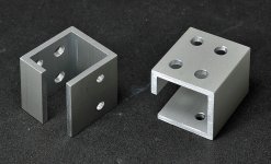
The biggest problem for me was finding suitable heatsinks, as none of the ready made solutions, which fit properly here, were efficient enough. Using enclosure to dissipate heat was of course my main goal when designing that board, and it works fine, but not everybody wants to place this circuit into an aluminum tubing.
I think I got a break today, when I figured out easy to fabricate custom heatsink: I simply use a section of 1 x 1 x 1/8 aluminum tubing and cut to 1.1" length with an opening on one side to mount devices. Additional access and mounting holes were also added. So far, this seems to work quite efficient and fits well 😉
I think I got a break today, when I figured out easy to fabricate custom heatsink: I simply use a section of 1 x 1 x 1/8 aluminum tubing and cut to 1.1" length with an opening on one side to mount devices. Additional access and mounting holes were also added. So far, this seems to work quite efficient and fits well 😉
Attachments
- Home
- More Vendors...
- Audio Sector
- The Phono Stage