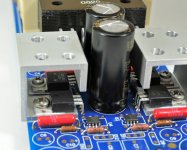
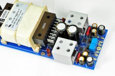
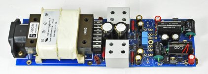
The LM317/337 are running quite cool and don't need much heatsinking; the MJE devices need a lot though.
When using 6-40 screws, you can tap through hole plated mounting holes in the board without a need for additional nuts.
While mounting LM317/337 and MJExxx on a same heatsink, at least one of the devices need to be isolated. I used the pad on LM317 and mounted MJE directly, using 4-40 and 6-40 machine screws respectively.
Attachments

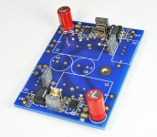
Please note position of 1k and 200R resistors. A trimpot can be installed in place of 200R for output voltage adjustments. Also, since J511 is hard to get, I added pads for Motorola 1N5314 which is a good substitute (K indicates Cathode)
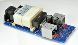
I use Nichicon FG 100/25 for all small bypass caps, I'm not sure yet, but they may be actually better than BG STD here. You may also notice that this time I didn't install the controversial cap across current source, instead, I have quick install sockets and be doing some comparisons 😉
When using PS board with phono section attached, C11/12 does not need to be installed as it installs in phono section instead.
For a free standing, separate PS only board, those caps are needed.
Using Variac, I checked what is the minimum voltage on main filter caps to still support 15V output: it looks like anything below 17.3V is already too low.
In case you have transformer with secondaries too low, simple adjust with R7/R8 for lower output voltage; OPA627 will work fine with 12V rails as well.
This concludes PS assembly, I will follow with phono board soon.
Attachments
Hi Peter
do you have a cost for the boards plus parts excluding black gate caps, and a time schedule for its release??
Luke
do you have a cost for the boards plus parts excluding black gate caps, and a time schedule for its release??
Luke
Peter, in an earlier post you say 2 PSUs is better than 1. Would that mean also 2 phono PCBs or are the power tracks easy to separate ?
You will need two PS boards, but could do with only one phono board by cutting it in half. The layout allows separate wire feed with dedicated bypass caps. I will be presenting it soon.
However, constructions wise, it's easier to simply populate one side only (phono) on each complete board.
The boards are $40/set, email me for parts cost.
However, constructions wise, it's easier to simply populate one side only (phono) on each complete board.
do you have a cost for the boards plus parts excluding black gate caps, and a time schedule for its release??
The boards are $40/set, email me for parts cost.
Last edited:
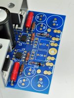
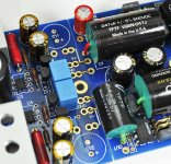
This is how I install resistors.
Price of Vishays is proportional to resistance value, and 330K resistor will cost more than $30pc, so I use nude Vishays only for 1k6 and 3k3.
Besides, I had very good results with Caddocks as well, especially in feedback and input shunt positions.
1k6 and 330K fit very nicely in a bottom layer, between the pins of op amps. I normally do not use 47R output resistor and take the signal directly from the second chip.
You will also see BG N for 10uF cap, short pin on +.
Attachments

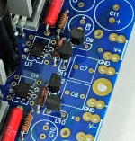
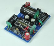
The caps go next, and here you see Teflon V-Caps. I didn't even consider using anything else in a phono stage of such caliber, but I can imagine that MIT RTX or Mundorfs will work almost as good. 😉
BTW, you will see "R" next to cap's pads, that indicates red lead, since those caps are directional according to manufacturer.
The filter caps (BG STD 100/16) have been moved from PS section in here. I use 2 sets of caps only if PS and phono board are separated by umbilical cord.
BTW, you will see "R" next to cap's pads, that indicates red lead, since those caps are directional according to manufacturer.
The filter caps (BG STD 100/16) have been moved from PS section in here. I use 2 sets of caps only if PS and phono board are separated by umbilical cord.
Attachments

All that is left is to supply power to phono board and we do it with 4 jumpers that can be put either in top or bottom layer.
And that's all, the assembly is completed.
And that's all, the assembly is completed.
Attachments
Last edited:
Peter,
What are the pluses and minuses of using the 47R resistor on the output? I have mine up and running and it sounds very good so far. Still need to play around a bit to see if I can minimize some hum.
What are the pluses and minuses of using the 47R resistor on the output? I have mine up and running and it sounds very good so far. Still need to play around a bit to see if I can minimize some hum.
Without resistor, the sound usually becomes more transparent. OTOH, that resistor terminates the output and acts as protection as well, so it's worth experimenting if the risks are worth the gains 😉
Still need to play around a bit to see if I can minimize some hum.
If you are using only the filter caps on phonoboard, see if adding C11/C12 on PS board helps.
BTW, stand alone PS board will not work properly without C11/C12: those caps are needed there to get the voltage right.
Last edited:
Thanks for the update Peter, I will play around with the output resistor after things are sufficiently broken in.
The PS board is separate from the phono circuit board, so I am using both sets of caps. With my Pearl MM/MC Phono, I had hum due to the proximity of the Hammond split bobbin xfmr to the audio circuit. I had to physically move the xfmr to a separate enclosure, I'm hoping that is not the case here as this is one of the first of these split bobbin xfmrs that does not buzz like crazy. I will have to fiddle around with that to see what my options are.
The other aspect I need to look at is whether or not to ground the tonearm to the phono circuit ground, right now the ground is floating.
Hi Peter, I found my problem which was a bad connection to the audio jacks.
Now I have sound coming out, but I used an MM cartridge and I get very low gain and muffed sound? I would think it would put out a lot of gain fro MM cartridge.
I tried to install my Zu Denon 103 on to test but accidently dropped it and destroyed the cantalever! Doh! So now I have no more MC cartridges to test it with.
Can somebody with an MM cartridge and this phono amp do a test to see if the gain is indeed low for MM cartridges? Thanks.
Can somebody with an MM cartridge and this phono amp do a test to see if the gain is indeed low for MM cartridges? Thanks.
It's usually house cleaners that kill cartridges.
The gain is based on internal impedance of your cartridge...maybe your MM is very high impedance?
"The output level is determined by the output amperage of the cartridge (output voltage divided by internal impedance)"
My cartridge is an Sumiko Antante P-76. It's got output of 2.5mv, output impedance of 1.7k ohm and load impedance of 47k ohm. What do you guys think?
I'm using Shelter 901 which has 0.4mV output and 12 ohm resistance; that produces 0.033mA output and is fine with 6dB gain line stage into F5 amp.
By comparison, your cartridge would produce 0.0015mA output, which is about 27dB less.
By comparison, your cartridge would produce 0.0015mA output, which is about 27dB less.
Hi Peter,
PhonoPre is running with Denon DL103 as well as with Lyra Dorian
without any hum etc. And the PCB is still not built in housing ;-)
How to connect the tonearm-ground? Directly soldered to ground
between BGStd 100???
The sound is great, and it´s even getting better....at the beginning
the heights where quite agressive.
Greetings Ulf
P.S. what kind of preamp do you use? you wrote about 6db amplifi-
cation.
How to connect the tonearm-ground? Directly soldered to ground between BGStd 100???
I guess that would work best.
I'm using this preamp: 6moons audio reviews: AudioZone PRE-T1
- Home
- More Vendors...
- Audio Sector
- The Phono Stage