Perhaps lifting the shield grounds from the case on the input side, but keeping them connected is correct? I'll make a drawing.
Last edited:
KOR952 WROTE below( I've tried it never better....., it's great for my Benz wood HO )
If there is more gain needed (+ 15dB), for instance when a Denon DL-103 is used, it is possible to change the second stage as follows.
R2 = R3 = 1k8
R4 = R6 = 1M
R5 = 100k
C2 = 3.3nF
C3 maybe the same (10uF) but may be changed to a 4.7uF
The gain of the first stage is R1 / cart. imp. x loss factor (due to the parallel RIAA cap)
For a DL-103 this will be 1620 / 40 x 0.9 = 36.45 x
The gain of the second stage is R5 / R3
For the original this will be 33k / 3.3k = 10 x
For the modified 15dB + version this will be 100k / 1.8k = 55.55 x
Output of a DL-103 with the original components = 0.3mV x 36.45 x 10 = 109 mV
Output of a DL-103 with changed components = 0.3mV x 36.45 x 55.55 = 607 mV
Difference in output is 14.9 dB
If you want less gain change R2 and R3 to a higher value, for instance 2.2k instead of 1.8k gives -1.74dB (0.818x) less gain.
RIAA filtering will not change while the values of caps and resistors are switched.
My 2 cents,
Ronald.
Last edited:
I wanted to revert to stock, and now the power supply is not working.
It showed +18.3 and -17.4 rails, I put in new opamps, it jumped around 0-10v, I turned it off, resoldered U1,Q2 Q1, Q2, and turned on again. Back to an unregulated 18 and 17 volts.
It seems the regulators have failed. The op amps were opez27.... I guess they are dead now too?
Any help getting this going again would be *greatly* appreciated, as this is my only phono section.
I've been taking my stupid changes out of the phono section. Never again will I doubt the skills of the designer. Rookie egotistical mistake. I apologize for that.
I've learned enough to know I don't know very much at all. The power supplies are back to original and have reasonable voltages. One last change is to remove is the added 15 dB gain from a post earlier in this thread....
Can someone tell me please..... how can a circuit with a shunt regulated supply and no ground connection hum? Is this a floating circuit? If this is a floating circuit, a ground loop breaker, (two diodes back to back with resistor and capacitor between the power supply zero volt line and the earth ground), should not be needed. Is that correct?
Also, should the ground lug for the TT be isolated from the chassis and connected to earth ground or should the ground lug be attached directly to the chassis which is already connected to earth?
I see about 3 mV of noise on the output with a scope attached.
Last edited:
fixed!
There are quite a few vias under parts. If you like to remove/replace a lot, you run the risk of damaging these vias. You then need to be creative.
There are quite a few vias under parts. If you like to remove/replace a lot, you run the risk of damaging these vias. You then need to be creative.
If you are going to build this, my recommendation is to match R2 and R3, the resistors between the Op amps.
Also, I believe that the sonics are related strongly to the quality of the caps. I tried a few, and in the 0.1 uF position, to my ear, Vcap is stellar
.
Also, I believe that the sonics are related strongly to the quality of the caps. I tried a few, and in the 0.1 uF position, to my ear, Vcap is stellar
.
phono stage
Hello Peter! there is no way to order this phono stage on your website. There are only amp kits. And, if I understood correctly, was it made only for MC cartridges? Is there no option for MM?It is for MC with 75dB gain.
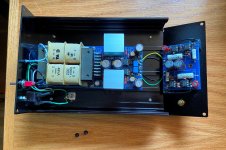
I've recently completed a version of Peter's MC phono preamp, details here:
mpbarney - AudioSector Moving Coil Phono Preamplifier
mpbarney - AudioSector Moving Coil Phono Preamplifier
Attachments
It seems that the working of this shelving low pass circuit is a bit misunderstood. With a pole at 50.5Hz and zero at 500.5Hz the gain difference offered by R4 and R5 should be 10x i.e. 20dB. For 10nF the ideal value of R5 would be 31k8. That sets the zero at 500.5Hz. The pole at 50.5Hz is defined by the sum of R4 and R5 together with C2. So to achieve the ideal factor the value of R4 + R5 should be 318k. This means R4 is 9x the value of 31k8 which is close to 286k. So for ideal RIAA curve choose resistors very close to these values.First stage:
1596R+47n >> best for 2121,73Hz
Second stage:
3k3 with 330k >> gain for DC 40dB. So for 1kHz will be 20dB less.
330k in NFB with 9,5nF gives 50,77Hz. 10n as the closest value >> 48,23Hz.
(330k/9)-3300=33366R >> 33k as the closest value. With 10n gives 482,29Hz.
3k3 with 10u cuts the lowest frequency.
When I simulate, the original values of 33k and 330k work just fine. You get a bit more gain difference (20.8dB instead of 20dB or, factor 11 instead of 10) which means a slight deviation that boosts the lowest frequencies 0.8dB more than required for the best theoretical RIAA. Other than that it follows RIAA very well.
R3 does not influence the curve at all. I only defines the gain.
Last edited:
And a little bit about the gain, I see a lot of questions about that:
The second stage gain is 19.2dB with the original resistors at about 1kHz. It is calculated by the parallel value of R4 and R5 divided by R3. That is 30k divided by 3k3.
The circuit is the 75dB version. So it is assumed that the first stage already gives 75-19.2=55.8dB gain. This is a factor of 616.6 and if you divide 1k62 by this number you obtain a value of 2.63ohm for the MC internal resistance needed to get 75dB gain at 1kHz. Everything below or above will respectively increase or decrease the gain of the phonoclone. E.g. the leson LS10 MK2 has 6.8 ohm which leads to 66.7dB gain in total. Lowering R3 to 1k78, increasing R1 to 2k26 and decreasing C1 to 33nF (to keep the second RIAA pole unaltered) will fix this problem and bring the gain back to about 75dB. Or, leave R1 and C1 the same and simply lower R3 (and R2) from 3k3 to 1k3. This should be no problem for the opamp since the signal levels at the output of the first opamp are still very low and even 1k3 will be easy to drive.
- Home
- More Vendors...
- Audio Sector
- The Phono Stage