Sounds good. It won't change the RIAA at all?
If not, I'll could try 6k6 or 33K3.
Darn! Those are nude vishay.
Caddock first then....
If not, I'll could try 6k6 or 33K3.
Darn! Those are nude vishay.
Caddock first then....
This will not affect RIAA. For initial gain adjustment you can use Dales or any other resistors.
Thank you Peter!
This is a *fantastic* sounding unit. I find my dual mono version very competitive with units in the $5-7K range.
This is a *fantastic* sounding unit. I find my dual mono version very competitive with units in the $5-7K range.
Grounding scheme and IC socket use
Peter, just few questions before I finish up:
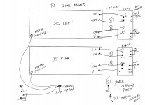
Grounding scheme I built 2 power supplies and separated the phono board as L/R to attach vertically and directly to the back of the RCA jack pairs (see pic). I want to make sure I have the grounding scheme correct. Since there are 4 common wires coming from the PS's and the phono boards are also separated, they all need to be joined somewhere to common.
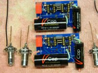
IC sockets on phono board I'm using copper V-Caps and all Vishay TX2575's except the 330k's (MK132) so I only want to solder this up once. I'm debating whether to socket the 4 op amps, but I'd also rather not have to de-solder machine pin dip sockets if there are problems. I do feel safer with sockets and like the option to try different ones in there. I already have 2 OPA627AP and 2 OPA637AP in dip packages so no SMD's will be used.
Tom
Peter, just few questions before I finish up:
Grounding scheme I built 2 power supplies and separated the phono board as L/R to attach vertically and directly to the back of the RCA jack pairs (see pic). I want to make sure I have the grounding scheme correct. Since there are 4 common wires coming from the PS's and the phono boards are also separated, they all need to be joined somewhere to common.
- Is it best to run separate 4 wires back from the 4 PS pads to the black binding post used for TT ground or should I just connect them right at the PS pads to each other?
- There should be no connection from the PS commons to chassis ground, correct?
- With only 1-2" from PS to phono I was going to leave the 100uf bulk caps (C4/5) off on the back of the phono boards. I put 100uf in place at the PS outputs. Any concern on this?
IC sockets on phono board I'm using copper V-Caps and all Vishay TX2575's except the 330k's (MK132) so I only want to solder this up once. I'm debating whether to socket the 4 op amps, but I'd also rather not have to de-solder machine pin dip sockets if there are problems. I do feel safer with sockets and like the option to try different ones in there. I already have 2 OPA627AP and 2 OPA637AP in dip packages so no SMD's will be used.
- What would the downside be, a little more DC offset, slight added stray capacitances?
- Would it even matter on this tiny board where inputs are connected directly to cart with a short low capacitance cable?
Tom
Attachments
As to the sockets, I'm using this type: http://www.diyaudio.com/forums/soli...n-38-preamp-chassis-scratch-8.html#post435714 and I'm not noticing any side effects. I noticed them first in Madrigal's reference DAC.
The sockets won't affect DC offset. The offset depends on a second chip (637), and if you sort them carefully, you can get it down to 1mV or so.
BigE was experimenting with wires and apparently they have quite an influence. I always keep the wires as short as possible, for signal I'm using this: http://www.diyaudio.com/forums/audi...-kit-building-instructions-2.html#post1514854
As to the grounds, connect wires from PS to phono boards directly, the grounds (+com/-com) connect together on phono board (com). Run wires from common point between filter caps (I'd rather place the 100uF cap on phono board that keep them at PS) to the binding post for TT ground. Keep the post isolated from the chassis. The chassis connects to IEC ground through one of the standoffs with a trace on PS pcb, so no additional wires needed.
I tried 3 kinds:
1) 18 gauge stranded
2) Teflon insulated 26 gauge Mundorf Silver/Gold Solid core
3) Teflon insulated 24 gauge Legenburg UPOCCC rectangular solid core
The 18 gauge stranded wire was noisy.
The Silver/Gold was *very* refined. Rock and roll did not....It took the life from the music, had good imaging and detail, but diminished bass, treble not very extended.
I settled on the copper legenburg. It has slam, no diminished bass, extended treble and live recordings sound live. Imaging and detail are still excellent, but now you can ROCK!
The difference on changing the wires was immediately evident.
Thanks for that comparison. In my case the wire from PS to phono board is only 1-1.5" and the phono board I/O is connected directly to the RCA jacks using solid wire cutoffs from the V-Caps. I wouldn't expect much difference with just that little bit of wire. What little there is would be Neotech I had laying around.
Tom
Tom
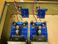
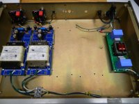
Mine is finally assembled in a test chassis. The board to the right is a CCCLCCC common mode choke filter (Felix).
There is very low noise, but there is a bit of hum that increases with volume even with metal cover and good separation (>12") to other AC components. I connected a ground wire from each phono board to the ground terminal then one from there to the TT metal chassis. My high gain Jolida JD9 has no hum using the same setup. Perhaps it's just too close proximity to unshielded AC inside the chassis and I'll have to try an umbilical?
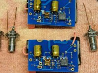
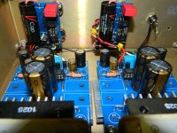
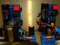
The CuTf's were easy to shoe horn in with split board and a little double stick tape. Just pinch off the insulation with finger nails to avoid nicks in the copper. I re-used the copper cutoffs to secure the RCA's to the back of the boards, which worked well.
There is plenty of gain for a Denon DL103R (14 ohm and 0.27mv output) with my Atma-Sphere line stage and amps. I tried a couple of test tracks, but further listening tests will have to wait until I return from the holidays in January.
Tom
There is very low noise, but there is a bit of hum that increases with volume even with metal cover and good separation (>12") to other AC components. I connected a ground wire from each phono board to the ground terminal then one from there to the TT metal chassis. My high gain Jolida JD9 has no hum using the same setup. Perhaps it's just too close proximity to unshielded AC inside the chassis and I'll have to try an umbilical?
The CuTf's were easy to shoe horn in with split board and a little double stick tape. Just pinch off the insulation with finger nails to avoid nicks in the copper. I re-used the copper cutoffs to secure the RCA's to the back of the boards, which worked well.
There is plenty of gain for a Denon DL103R (14 ohm and 0.27mv output) with my Atma-Sphere line stage and amps. I tried a couple of test tracks, but further listening tests will have to wait until I return from the holidays in January.
Tom
Attachments


Thanks for that comparison. In my case the wire from PS to phono board is only 1-1.5" and the phono board I/O is connected directly to the RCA jacks using solid wire cutoffs from the V-Caps. I wouldn't expect much difference with just that little bit of wire. What little there is would be Neotech I had laying around.
Tom
My wiring is about 3-4 inches long. The differences are huge.
There is very low noise, but there is a bit of hum that increases with volume even with metal cover and good separation (>12") to other AC components. I connected a ground wire from each phono board to the ground terminal then one from there to the TT metal chassis. My high gain Jolida JD9 has no hum using the same setup. Perhaps it's just too close proximity to unshielded AC inside the chassis and I'll have to try an umbilical?
I wouldn't suspect AC components, it's probably the grounds and some experimentation is needed here. What happens when ground wires are disconnected from the terminal? What happens if the terminal is connected directly to chassis and only TT ground attached to terminal?
I had similar noise when the TT ground lug was connected to the chassis. When the TT ground lug was not connected to the chassis, the problem was gone.
No change.I wouldn't suspect AC components, it's probably the grounds and some experimentation is needed here. What happens when ground wires are disconnected from the terminal? What happens if the terminal is connected directly to chassis and only TT ground attached to terminal?
Here is what I did tonight:
- Removed both black phono board ground wires from black ground terminal and also separated them from each other (floated)
- Removed TT ground from isolated black ground terminal (floated)
- Removed AC power to the TT
- Removed AC filter board and input circuitry from the back right of chassis
- Hardwired AC directly to the 2 power supplies in front of the chassis. IEC is fed there to the front instead of the back right.
- Re-dressed all cables to ensure they are separated away from AC sources
There was no change at all from these steps. One channel slightly more hum than the other, but not much. Basically gain is fairly high, to the point where hiss is starting to be evident when the hum starts.
When I remove the input cables from the preamp or remove the headshell all is quiet, which I suppose makes sense. This old Empire tonearm cable and arm wiring does not have any shielding or a separate ground on it. The ground wire from the TT is tied to the plinth/chassis itself, a few inches from the arm base. I have a new TT and tonearm on the way so will replace that very soon.
I guess it's time to separate the power supplies from the phono boards, recheck soldering, and see what happens. It's just a pain because they're both hardwired.
The strange thing is I actually built up a PhonoClone3 without a case and I have a stock Jolida JD9 and neither of them hums with the same TT/arm.
tms0425,
Where does the ground wire go from the TT to the phono section?
On mine, I did not cut the boards in half, and populated only one side. This meant, I could use the regular positions for the PS caps on the phono circuit board. The ground from the TT goes to PS common ( right between the two caps on the board).
I had one wire from each phono board over to the insulated ground terminal. TT ground was connected there.tms0425,
Where does the ground wire go from the TT to the phono section?
On mine, I did not cut the boards in half, and populated only one side. This meant, I could use the regular positions for the PS caps on the phono circuit board. The ground from the TT goes to PS common ( right between the two caps on the board).
I had one wire from each phono board over to the insulated ground terminal. TT ground was connected there.
Where is is attached on the phono board? Mine is attached to the GND side of the two caps on the phono circuit. See Peter's photos on post #1
Last edited:
- Home
- More Vendors...
- Audio Sector
- The Phono Stage