Hmm, WRT layout, a BLH is basically a large vent, so just like a multi-resonant vent system, its output will be lower Q, comb filtering with the driver’s output over a wider BW same as occurs with an Ultraflex or Onken alignment, only more audible due to the BLH’s greater acoustic loading to offset baffle step loss. This may require more internal damping though, somewhat defeating the purpose of all the extra woodworking.
Another potential problem is the increased HF directivity of these smaller horns, so just like with the Ultraflex or Onken alignments, placing the vents acoustically close around the driver to create a larger perceived point source with careful consideration of any local boundary conditions will be key to getting the most out of all the effort required with minimal/no horn path damping, though critically damping the summed terminus in the form of a grill may still be required to damp down any ‘ringing’ in the critical acoustic XO BW.
All things considered then, designing based on a fairly high Qt system will lower the acoustic XO point, shortening the horns to minimize both the woodworking and the HF issues, so experimenting with a small, relatively high Fs driver or its [driver+high output impedance] equivalent seems the way to go.
GM
ok - that section of the graph paper sketch was a bit confusing. Am I correct that horns #4 and 5 do not get the first few bends and go straight down from the plenum?
That is correct. Horns 4 and 5 come straight down from the front of the plenum chamber. Regarding arrangement of horns, I think the shorter ones should be towards the center ( as freq are more directional), the longer ones can be on the sides.
Yes, that 20 square inch area leads to the plenum which then feeds the individual 5 throats for each of the horns.
horn 1
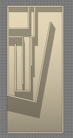
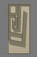
Here is version 2 of horn 1. I tried to follow the graph paper sketch.
The grid on this one is 1".
To me it seems a bit cramped just above the angled panel which forms the top of the mouth.
Should I move the bottom of the U above it up an inch or two?
Colin
Here is version 2 of horn 1. I tried to follow the graph paper sketch.
The grid on this one is 1".
To me it seems a bit cramped just above the angled panel which forms the top of the mouth.
Should I move the bottom of the U above it up an inch or two?
Colin
Attachments
horn 01 revised
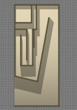
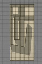
Here is an adjustment to the first horn.
Basically, I just moved the first U bend up 3" so the horn below it would be continuously getting bigger.
There is still kind of a pinch point to the lower right of the U.
I will try angling the bottom of the U next as an alternate.
CG
Here is an adjustment to the first horn.
Basically, I just moved the first U bend up 3" so the horn below it would be continuously getting bigger.
There is still kind of a pinch point to the lower right of the U.
I will try angling the bottom of the U next as an alternate.
CG
Attachments
Colin,
Thanks for making these 3d models. Keep in mind that the simulation results that I have are based on the dimensions on my hand drawn sketch - which is actually drawn close to scale with each square equal to 2 inches x 2 inches. As drawn, I don't think I have any serious pinch points. You can't just move things around - need to preserve close to the original profile, path length, and expansion ratios. When you move things around, it can have a drastic change on the resulting frequency response.
Thanks for making these 3d models. Keep in mind that the simulation results that I have are based on the dimensions on my hand drawn sketch - which is actually drawn close to scale with each square equal to 2 inches x 2 inches. As drawn, I don't think I have any serious pinch points. You can't just move things around - need to preserve close to the original profile, path length, and expansion ratios. When you move things around, it can have a drastic change on the resulting frequency response.
I am trying to follow the drawing, just adding the third dimension, and material thicknesses.
So far all the panels are 0.5" thick, thinking an eventual plywood build.
CG
So far all the panels are 0.5" thick, thinking an eventual plywood build.
CG
horn 01 v004
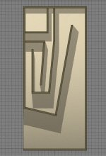
here is an alternate for horn 01.
This is an attempt to keep things mostly the same size while removing corners and edges, so the horn is smooth on the inside.
I eliminated the hole in the bottom of the plenum so that the passage goes straight through - no edges to work around.
Should I block off the lower part of the plenum which is not used in this horn?
Thanks for putting up with my trial and error process of learning how to design horns.
I really and just trying to learn...
If you have Photoshop, just make notes on these, and re-post them.
CG
Attachments
horn v005
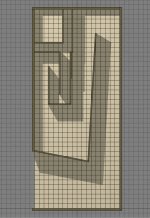
Ok -
I reduced the material thickness to 0.25" and adjusted everything a little to be closer to X's graph paper dimensions.
The grid in this is 1".
If this is good, the rest of the horns will be pretty fast to build off of this template.
Colin
Ok -
I reduced the material thickness to 0.25" and adjusted everything a little to be closer to X's graph paper dimensions.
The grid in this is 1".
If this is good, the rest of the horns will be pretty fast to build off of this template.
Colin
Attachments

Colin,
That looks really good! I think that matches my sketch. I would use at least 1/2 in plywood as 1/4 in is tough to get a good joint without lots of supporting blocks and braces. You will need braces in either case. Good luck on the build?
X
That looks really good! I think that matches my sketch. I would use at least 1/2 in plywood as 1/4 in is tough to get a good joint without lots of supporting blocks and braces. You will need braces in either case. Good luck on the build?
X
panel thickness
I chose 1/4" so the dimensions would be closer for foam core builders. And, the material thickness was having an impact on how easy it was to match your dimensions and still be physically build-able.
The outer box is 1/2" still.
I may make a prototype with a plywood outer box and baffle, and foam core inner dividers as step one, and then decide if a full wood one will be next.
More soon -
Colin
horn 02 v001
Hi -
Here is horn 02 - identical to horn 01 except the central U bend is 7 inches shorter.
The space below is quite large now - is this OK? Should we move the angled bottom of this up to make the section of the horn narrower at that point, and therefore getting ever bigger?
Colin
Hi -
Here is horn 02 - identical to horn 01 except the central U bend is 7 inches shorter.
The space below is quite large now - is this OK? Should we move the angled bottom of this up to make the section of the horn narrower at that point, and therefore getting ever bigger?
Colin
Attachments
I was thinking also that, per your suggestion, X, the order of the horns be
1,3,5,4,2.
This has the shortest in the middle
Would this be correct?
Colin
1,3,5,4,2.
This has the shortest in the middle
Would this be correct?
Colin


- Status
- Not open for further replies.
- Home
- Loudspeakers
- Full Range
- The PANPIPE (Pentahorn) BLH Speaker