Tomlang,
Do you have any more Sketchup drawings of the Panpipe yet? I think folks may start on this once good drawings are available. Thanks for making them.
Do you have any more Sketchup drawings of the Panpipe yet? I think folks may start on this once good drawings are available. Thanks for making them.
the outside of this enclosure reminds me of the "Mello Monster" in size
http://www.diyaudio.com/forums/full-range/134706-mellow-monster-3.html#post1685968
http://www.diyaudio.com/forums/full-range/134706-mellow-monster-3.html#post1685968
Tomlang,
Do you have any more Sketchup drawings of the Panpipe yet? I think folks may start on this once good drawings are available. Thanks for making them.
I had a computer meltdown but have since reconstructed all my files. I kind of lost interest in this for now, but if somebody raises their hand that wants to build this, I will continue on with this drawing.
I am happy to attempt to mock up the Pan Pipe design as a simple 3D model, if I can get a little help in understanding how the driver chamber connects to the "plenum manifold" chamber leading to the horns. If I can understand this section, it will not be that hard to attempt to connect these openings via independent horns to the horn mouths along the bottom front of the 25" x 18" x 42" overall box.
All the dashed lines on the side of the drawing in post #1009 on the cornu thread are a bit confusing, but to me this signifies some flexibility in routing the 5 horns to the front, filling both the the width and depth of the overall cabinet. Is this right?
Sounds like a fun puzzle.
Would it be reasonable to assume a simple plywood box for the outer volume, with foam core dividers and chambers set within this? (and maybe a plywood panel to hold the driver connected strongly to the big box.
Let me know your thoughts - obviously I am an extreme amateur, having still not even completed my first set of cornus. But, I can model things in 3D on my computer pretty fast, and can perhaps improvise some clever solutions.
Colin
Initial 3d model mock up
xrk971 -
Here is about 20 minutes of modeling in 3D. Super simple.
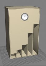
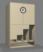
I started attempting to make the simplest possible version of your sketch, but then, reading your description more carefully and seeing that different size mouths are needed for different size horns, and with some aesthetic instincts to make the design visually refer to a Pan Pipe, I made each horns mouth a different height. this might complicate things later, but I thought I would see what you thought.
(The speakers would be mirror images...)
There is some aesthetic appeal to 4 out of 5 being the same height and only one bigger. Could there be 4 the same height all the way across, and one big full width one across the bottom?
Colin
xrk971 -
Here is about 20 minutes of modeling in 3D. Super simple.
I started attempting to make the simplest possible version of your sketch, but then, reading your description more carefully and seeing that different size mouths are needed for different size horns, and with some aesthetic instincts to make the design visually refer to a Pan Pipe, I made each horns mouth a different height. this might complicate things later, but I thought I would see what you thought.
(The speakers would be mirror images...)
There is some aesthetic appeal to 4 out of 5 being the same height and only one bigger. Could there be 4 the same height all the way across, and one big full width one across the bottom?
Colin
Attachments
Colin,
I like what you have done - nice work there. However I don't think I said that the mouth sizes were different. The mouth sizes are all the same in fact at 5 in wide x 12 in tall and for the reason that the mouth controls the expansion ratio and hence bass gain for that particular frequency band. In order to keep the levels even, the mouths are the same - what is different are the lengths. Tom Lang has a good drawing of one set of channels - that is the idea. The throat entrances to the beginning of each horn or pipe needs to follow the prescription given and locate it somewhere convenient on the driver chamber wall at the bottom that forms the top wall of the horns entry region. I will try to sketch out something in more detail when I get some time. Thanks for taking interest and reviving this thread.
Regards,
X
X - the very top post says "Horns mouth 1 (longest) will be 12 in tall x 5 in wide, the rest are all 8 in high x 5 in wide." This is what got me started on thinking of aesthetic interpretations of expressing the range of horn sizes on the exterior, which I thought would be a cool looking way of expressing how much complexity is going on inside.
Will try to keep my creative instincts in line with your horn science.
looking forward to more sketches.
CG
Will try to keep my creative instincts in line with your horn science.
looking forward to more sketches.
CG
the importance of a side view!
This design now makes sense to me. I will now undertake a simple 3d model.
This design now makes sense to me. I will now undertake a simple 3d model.
Colin,
Ok - so do you think you understand what my drawing and design is saying now? If I get some time I may take this model up again and try to refine the response to make it less pesky at the low bass extension. Chamber is probably too big.
Let me knowing you need more info to make your 3d model.
Thanks,
X
I saw the side view and wrote my post, but now I don't see it. What thread and what post # was it?
CG
CG
I saw the side view and wrote my post, but now I don't see it. What thread and what post # was it?
CG
This thread post 13 is my hand sketch. Post 29 is Tom Lang's cad drawing.
My hunch is to ignore all the details in Tom's sketch up file, nice as it is, as it is only one section, and go for a full 3d model of all 5 horns.
Are your original sketches available at higher res?
We need to rename this project the Pan Pipe, I think. Pentahorn is the 5 sided build Cal posted a photo showing.
Nothing satanic about this project.
CG
Are your original sketches available at higher res?
We need to rename this project the Pan Pipe, I think. Pentahorn is the 5 sided build Cal posted a photo showing.
Nothing satanic about this project.
CG
X -
Did you have an idea of the order of the pipes from one side to the other? Should they be 1, 2, 3, 4, 5, or the biggest pipe in the middle or to one side?
Biggest to the outside, and then smaller until the smallest on the inside and symmetrical on the other speaker?
I realize that my design criteria is, again, purely aesthetic.
CG
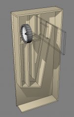
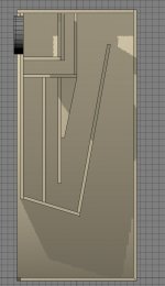
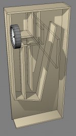
Here is version 01 of horn 01 -
In the left most position of the 5 horns. (this is still up for debate...)
A little hard to grasp visually as it is only a 1/5th slice out of the whole speaker.
I think it is best if I treat each horn individually, and figure out the final dimensions of each part at the end.
Can I assume a 1/2" thickness for the dividing panels? (For an ultimate wooden version... Foam core prototypes will have to scale to the middle dimension of each part...)
If I were building a prototype, I would go with 1/2" plywood for the outer box, and 3/8" for the foam core.
For the final. 3/4' plywood outer box and 1/2" plywood inner dividers..
Grid is 1".
CG
Attachments
Last edited:
Colin,
Nice work ! Thanks for taking this on. This is a good start and I am glad you are eager to get going on the model. The 3d model as you have drawn it though is not correct. The horn path needs to have another bend in the front. Look at Tomlang's 2d drawing to get an idea. I will draw some more sketches for you to work with to make this clear but the "flow" from the driver chamber goes to the plenum which you have correct then that goes to the narrow channel from the top (same one you show connected to larger exit) then turns 180 up and to the front then 180 down and to then 90 back to the main horn mouth exit. Note that the passages from chamber out needs to gradually expand. You show the flow contracting as it goes out. That should get you going on the general layout and architecture.
Nice work ! Thanks for taking this on. This is a good start and I am glad you are eager to get going on the model. The 3d model as you have drawn it though is not correct. The horn path needs to have another bend in the front. Look at Tomlang's 2d drawing to get an idea. I will draw some more sketches for you to work with to make this clear but the "flow" from the driver chamber goes to the plenum which you have correct then that goes to the narrow channel from the top (same one you show connected to larger exit) then turns 180 up and to the front then 180 down and to then 90 back to the main horn mouth exit. Note that the passages from chamber out needs to gradually expand. You show the flow contracting as it goes out. That should get you going on the general layout and architecture.
- Status
- Not open for further replies.
- Home
- Loudspeakers
- Full Range
- The PANPIPE (Pentahorn) BLH Speaker