Also another thing I noticed: during both power down and power up there is a very noticeable "thump" noise on the left channel, the very same channel that has already died twice. Coincidence?
Just a random thought - the paralleled output stage relies on all the opamp input pins making good contact to the socket and the socket being solidly soldered into the pcb. Any dodgy connection on any of the inputs in the output opamp will lead to the two halfs of the opamp fighting each other through two 1-ohm resistors, which would be bad news.
Maybe check the sockets and solder joints on the left output opamp? Its possible to bend in the internal spring contacts in an IC socket by misalignment. Its usually important to de-splay the pins of a DIP IC before inserting into a socket to make insertion easier.
what would happen if the 1 ohm resistors were bypassed in this, meaning the 2 op amp outputs would have a direct connection? AFAIK being nonidentical one op amp would do more of the work, but to what extent?
The extent would depend on the internal imbalances within the chip. So its an unknown. Given that the output impedance at the pins is going to be a fraction of an ohm, then any even slight difference in DC offset between the two would cause correspondingly large currents to flow.
You could perhaps monitor the current draw of the opamp and see if it increases with the output pins shorted. That would be a sure sign of imbalance. You would have to do the same at AC as well using say 10 or 20kHz.
Even one tenth of an ohm would make a big difference in this.
You could perhaps monitor the current draw of the opamp and see if it increases with the output pins shorted. That would be a sure sign of imbalance. You would have to do the same at AC as well using say 10 or 20kHz.
Even one tenth of an ohm would make a big difference in this.
DS shows max of 6mV input offset voltage, if we assume they are all within spec we can treat that as worst case. How do we get the current from that?even slight difference in DC offset between the two would cause correspondingly large currents to flow.
Trying to figure out what the resistors are actually doing to balance the load (the O2 page explains what they for but not how)... maybe obvious to most?
Btw I dont have my O2 anymore to test current draw, trying to figure out how critical the 1Rs are for building simple buffer with OPA1688 with no low values Rs on hand. the O2 being intended for portable use (and well engineered in general) I can see how efficiency is very important but here the only concern is performance.
edit: I missed the further explanation on O2 page, so with 6mV offset with its output impedance of 0.1ohm you would get a huge 60mA of current
Also since the plan was to parallel more than 2 OPA1688, the output impedance goes with more resistors while load balancing effect stays the same.
The tighter tolerance for offset with OPA1688 means you could probably use 0.5R for these resistors safely, but probably not much to gain from it.
Not sure about output impedance of the OPA1688, its only gives open-loop Z out in the DS.
Last edited:
Remember that any value of offset (even 0.0001 pico volts) into zero ohms generates infinite current.
As far as the O2 goes, all you need do is measure the DC voltage difference between the two opamp output pins per package and divide that result by your chosen total series resistance.
So 6mv offset and 12mv offset per opamp would generate a voltage difference of 6mv and a current of 3 milliamps if the standard 1 ohms were used. That's acceptable.
Practicalities such as pin to socket resistance and also print and wire resistance play a big part as you reduce values.
If the OPA1688 has an output impedance similar to the 4556 then it may well be possible to go without resistors, aslong as the chips are checked to be within the typical specs(0.25mV).
It makes sense to just build the circuit and check the current draw without Rs first.
It makes sense to just build the circuit and check the current draw without Rs first.
I would think the resistors do more good than harm tbh. DC is one thing, what about dynamic performance at HF where there may be more significant variation between the two opamps.
In the same way they help at DC.
The final value of current flowing due to any differences between the two opamps depends entirely on the voltage difference between the two output terminals. That will almost certainly become more pronounced at higher frequency.
All this is as much practical as it is theoretical.
Link the resistors out on the board and you will still have a few tens or even hundreds of milliohms still present due to the socket and print resistance, and that will go a long way to mitigating the possible problems.
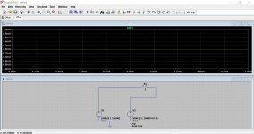
Look at these. Two voltage sources (they could be opamps) feeding a resistor between their outputs. The trace shows the current in the resistor.
Image 1 shows no current flow in a 2 ohm resistor. The signals are identical.
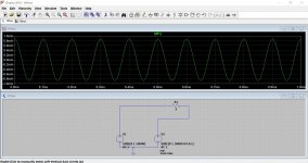
Image 2 shows a 0.1 or one tenth of one degree phase shift in the signal of one of the voltage sources. Look at the current now.
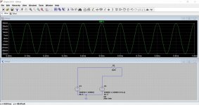
Image 3 shows the resistance now at 50 milliohms (that's a reasonable value for a bit of short thin print). Now look at the current.
In practice the higher the frequency and the more the opamps will differ. And remember this is showing just 0.1 degree difference in phase.
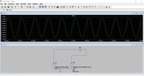
Image 4. If we add a 1 millivolt difference in amplitude per opamp from the 1 volt we used for the above images it gets even worse.
So the resistors are a vital component to even things out. They will also help with stability because even a couple of ohms is enough to tame any unpredictable HF oscillation that might occur.
Image 5. Same set up as image 4 but now back to 2 ohms resistance.
Image 1 shows no current flow in a 2 ohm resistor. The signals are identical.
Image 2 shows a 0.1 or one tenth of one degree phase shift in the signal of one of the voltage sources. Look at the current now.
Image 3 shows the resistance now at 50 milliohms (that's a reasonable value for a bit of short thin print). Now look at the current.
In practice the higher the frequency and the more the opamps will differ. And remember this is showing just 0.1 degree difference in phase.
Image 4. If we add a 1 millivolt difference in amplitude per opamp from the 1 volt we used for the above images it gets even worse.
So the resistors are a vital component to even things out. They will also help with stability because even a couple of ohms is enough to tame any unpredictable HF oscillation that might occur.
Image 5. Same set up as image 4 but now back to 2 ohms resistance.
Attachments

thanks for the great explanation, so the resistors are limiting the current from those voltage imbalances rather than affecting the voltages and correcting those imbalances.
Yes, absolutely that's how it works. A little voltage across a very very low resistance generates lots of current. Add even a small resistance and the current just falls away.
The resistors don't correct anything as such, they just swamp the unwanted effect so that it becomes a non issue.
The resistors don't correct anything as such, they just swamp the unwanted effect so that it becomes a non issue.
Mooly I noticed you did some tested a while back with LM4562 driving lower impedance loads.
Taking into account the lower output current, Do you think there is much reason the LM4562 would be any worse (THD+N) than the OPA1688 into 32 ohm loads?
It seems like the OPA1688 advantage is the increased output current compared to older generation of TI's audio op amps so it can drive down to 16ohm, in addition to being a low power CMOS device this makes it usable for driving low impedance, ultra high sensitivity IEM headphones in a portable application... but that is probably oversimplfying it.
While the LM4562 datasheet has no mention of low impedance loads, the OPA1688 still reflects dramatic increases in distortion into low impedance loads.
To clarifiy, any amplifier will distort more when delivering more power, but is there some reason the LM4562 or similar op amp intended by designer for ultra low distortion at high impedance would be worse?
Last edited:
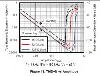
This was about the closest anything came to answering that question, but still a long way off. OPA2134 already being slightly higher in distortion also shows almost double the distortion from a 2k to 600 ohm load in the DS. LM4562 shows no increase, same as OPA1688. From excessive heating of OPA2134 at 32 ohm in those tests its not even safe to say that is the true performance of the OPA2134.
Last edited:
I wouldn't like to give a definitive answer on that tbh.
The OPA is classed as 'rail to rail' which means it will ultimately deliver more voltage into a given load for a given supply... particularly when talking of low voltage rails anyway.
As to distortion comparisons into low impedance loads, well I would say the 4562 will distort well before the OPA as levels rise and again, particularly so on lower supply voltages. The data sheet shows the output set at 1vrms into 16 ohms which is a peak current of 88 milliamps. And all that on a supply of -/+5 volts. I'm pretty sure 4562 wouldn't achieve that.
are you sure you read that right? OPA1688 has short circuit output current 75mA , cant find where it says 1vrms into 16 ohm.
''rail to rail'' is another impressive practical advantage for the opa1688 I hadnt considered, for desktop use with high voltage rails there shouldnt be any issues there.
If its mostly down to output current that is a problem which quickly disappears when you consider paralleling.
''rail to rail'' is another impressive practical advantage for the opa1688 I hadnt considered, for desktop use with high voltage rails there shouldnt be any issues there.
If its mostly down to output current that is a problem which quickly disappears when you consider paralleling.

Source: http://www.ti.com/lit/ds/symlink/opa1688.pdf
As based on http://www.ti.com/lit/ds/symlink/lm4562.pdf LM4562 doesn't seems to love load resistances higher than 500 Ohms.
I had used LM4562 and OPA1688 in the O2 (one of the very first DIY experiments) and the sound of LM4562 was much nicer and cleaner, but it sounded like it struggled with the 50r cans compared to OPA1688, most noticeably at higher levels (these were very low sensitivity planar HPs). I had always wondered if rebuilding the O2 output stage with twice the LM4562s would be enough to fix that.
With OPA1656 around the corner it would be a better idea to see how they compete with these OPA1688, OPA1656 has better distortion figures comparable to LM4562 though I feel like it had more to do with BJT input than distortion as LM mustve been distorting more into those loads.
With OPA1656 around the corner it would be a better idea to see how they compete with these OPA1688, OPA1656 has better distortion figures comparable to LM4562 though I feel like it had more to do with BJT input than distortion as LM mustve been distorting more into those loads.
Greetings,
New member and semi-novice builder here. I assembled an O2 from Head 'n' HiFi recently. Been absolutely loving it for several weeks. Such detail!
It has gone wonky on me. 🙁
I thought it was the output jack as it sounded like the headphone plug was not able to properly seat. A really loud pop, some clicks and a very faint audio signal if inserted just so. Tested all of the other connections I was able to. I assume the input jack is OK.
Well, I replaced the jack with the identical bit from Mouser. Was an easier swap than I'd have thought. I bought 4 of them as I do not have a great feeling about the longevity of the jacks.
I get the exact same result with the replacement. :/ What might you O2 gurus suggest to try troubleshooting-wise next?
I really miss the little box!
- Home
- Amplifiers
- Headphone Systems
- The Objective2 (O2) Headphone Amp DIY Project