i just see that i mixed up the parts for U5 and U6.
Tomorrow i will swap them(after going insane in the process of desoldering 🙄), and hope that it didn't damage the other components.🙂
Tomorrow i will swap them(after going insane in the process of desoldering 🙄), and hope that it didn't damage the other components.🙂
Getting them reversed shouldn't damage anything else, but whether the regulators are OK though remains to be seen.
yay! 😀
it works now(and measures correctly aswell, forgot to set the multimeter to VAC for D4 before, so i got "0V" there
 ).
).
Desoldered U5 and U6 with the "solder blob over all pins"-method. 😛
it works now(and measures correctly aswell, forgot to set the multimeter to VAC for D4 before, so i got "0V" there
Desoldered U5 and U6 with the "solder blob over all pins"-method. 😛
 and thanks for letting us know it all worked out OK.
Just a small question again:
I left out R19 and R23, and installed 1K ohm resistors to R17 and R21, is it correct that this will give 1x gain(no gain) with the gainbutton out, and 2.5x gain with it in?
At least it works like this, but i just want to make sure, that this doesn't compromise anything.
thx 🙂
I left out R19 and R23, and installed 1K ohm resistors to R17 and R21, is it correct that this will give 1x gain(no gain) with the gainbutton out, and 2.5x gain with it in?
At least it works like this, but i just want to make sure, that this doesn't compromise anything.
thx 🙂
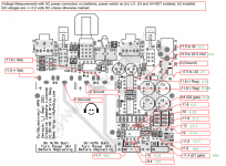
I've been working on building an o2 and i've run into an issue. The problem is that I just get a hum instead of audio when it's plugged into my wall and when it's on battery (bargin bin 9volts) I can make out the music faintly. turning the volume or gain on does nothing for the volume on either power source. I've been going through the troubleshooting steps and my resistors are fine, my ac adapter is putting out 18vac and following this NwAvGuy: O2 Details I pass all steps until get to step 19 and at that point my voltage is 2.3 on u4 pin 4 instead of -11.8. u4 pin 8 however is fine at 11.8. I've double checked u2 and it's the right part, in the right direction and the pins on the socket look like they are soldered fine. Is this a failed u2 part as the guide suggests or possibly something else? Also I did make one substitution on r16 and r22, instead of 1.5K Ohm >= 1/8 Watt 1% I got 1.k Ohm 1/2 watt 1% because the other part was on backorder. Here are some pictures if it helps o2 - Album on Imgur .
Thanks for any help,
Sean
Thanks for any help,
Sean
Thanks for the fast response and that guide (I didn't see it before). I got around to going through it today and It's still the same result, pin 8 on u4, u3 and u1 are reading low/no voltage so either my u2 is bad or more likely my q2 is bad. I have more op amps on the way, hoping I can find some mosfets locally.
-Sean
-Sean
Are the voltages correct on U2 pins 4 and 8 (as measured from audio ground) ?
You should have around +11.5 volts on pin 8 and -11.5 on pin 4
You should have around +11.5 volts on pin 8 and -11.5 on pin 4
More...
Measure and record the voltage on each pin of U2. Copy and paste this and fill the voltages in.
Pin1=
Pin2=
Pin3=
Pin4=
Pin5=
Pin6=
Pin7=
Pin8=
Measure and record the voltage on each pin of U2. Copy and paste this and fill the voltages in.
Pin1=
Pin2=
Pin3=
Pin4=
Pin5=
Pin6=
Pin7=
Pin8=
With the power on and only u2 put in the socket I get the following readings.
u2
Pin1=-11.85
Pin2=-8.68
Pin3=-10
Pin4=-11.86
Pin5=-10
Pin6=-11.86
Pin7=7
Pin8=11.87
u4
pin 4=-0.8
pin 8=11.87
u2
Pin1=-11.85
Pin2=-8.68
Pin3=-10
Pin4=-11.86
Pin5=-10
Pin6=-11.86
Pin7=7
Pin8=11.87
u4
pin 4=-0.8
pin 8=11.87
It looks like the problem is Q2. Just make sure that the -11.8 volts is reaching the source of Q2.
Thanks again for the help. I measured the 3 pins as -11.88, -1.4 and 7.0 (ordering from the left to right where the left most pin is closest to the battery area on the pcb). I'd like to go to my local frys electronics and pickup a replacement however they only carry nte and not fairchid so I have no idea what part number to look for, what should I be looking for in a replacement part? This is the small list of parts they have Fry's Electronics | .
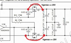
The two FET's used in the O2 are unusual types because they can withstand a 25 volt differential between gate and source. Most devices are around -/+ 20 volts or less.
The basic requirement for the FET is that it must be an N channel device, it should have a very low 'Rds' (anything under 1 ohm would be OK for the O2) and it MUST be capable of withstanding a gate-source voltage of at least 25 volts. That last bit is the problem.
It may well be possible to do a simple modification to enable it to work with more common devices but I'd have to study the circuit and see what was possible.
What I would do to begin with is to link out both FET's from Drain to Source and then test the amp and make sure it all works correctly.
Attachments
- Home
- Amplifiers
- Headphone Systems
- The Objective2 (O2) Headphone Amp DIY Project