I just want to drop by and say hi to all the O2 gang around. I just recieved all the goods from Mouser and I´m getting impatient for the PCB to arrive along with a front panel all from JDSlabs.
Hopefully I´ll start populating the board in a pair of weeks...my first DIY amp, more anxious than nervous LOL, anyhow keep the good work chaps!
Cheers from Mexico.
Rob.
Hopefully I´ll start populating the board in a pair of weeks...my first DIY amp, more anxious than nervous LOL, anyhow keep the good work chaps!
Cheers from Mexico.
Rob.
I also just recieved my parts from Mouser and Id like to start building today but I think I may have ordered an incorrect part for the Q1/Q2 Mosfets. The part numbers are the same as on the BOM but they are two different package types. Part numbers are FQPF10N20C and FQU11P06TU. Is this right? Any help would be greatly appreciated. Thanks
An externally hosted image should be here but it was not working when we last tested it.
As long as the part numbers on them correlate to the BOM, then the packaging won't make a difference 🙂
I also just recieved my parts from Mouser and Id like to start building today but I think I may have ordered an incorrect part for the Q1/Q2 Mosfets. The part numbers are the same as on the BOM but they are two different package types. Part numbers are FQPF10N20C and FQU11P06TU. Is this right? Any help would be greatly appreciated. Thanks
It's correct. The two mosfets used in the O2 are different package types.
what could be the cause of the volume control not working? I'm hearing only the slightest level of signal with music on and the pot making rustle noises when turned.
opamp voltages all seem in order ( I'm running the amp on batteries currently and the numbers are apprixmately 70% of AC operation) and i've desoldered the pot and it meausres fine it seems- 9.71kohm in both channels...
any advice is very appreciated.
opamp voltages all seem in order ( I'm running the amp on batteries currently and the numbers are apprixmately 70% of AC operation) and i've desoldered the pot and it meausres fine it seems- 9.71kohm in both channels...
any advice is very appreciated.
what could be the cause of the volume control not working? I'm hearing only the slightest level of signal with music on and the pot making rustle noises when turned.
opamp voltages all seem in order ( I'm running the amp on batteries currently and the numbers are apprixmately 70% of AC operation) and i've desoldered the pot and it meausres fine it seems- 9.71kohm in both channels...
any advice is very appreciated.
Post some photos of the board, someone might notice something.. It sounds like you have something very fundamental wrong..
A rustling noise while turning the volume pot is not unusual. For the low signal, have you checked the input and output jacks for continuity (0 Ohms)?what could be the cause of the volume control not working?
Edit: Also, like Mr. Slim said, pictures help sometimes.
Last edited:
Best i could do with my phone at night:
ImageShack® - Online Photo and Video Hosting
ImageShack® - Online Photo and Video Hosting
ImageShack® - Online Photo and Video Hosting
I should note that it's not entirely my build, a buddy of mine did all the the inputs, teminals and pot and most of the resistors and i did the rest. He used some generic solder that flow more freely than the recomended solder from the BOM that i've been using. i suspected that it might have damaged the pot with the but as i've said it measures quite ok.
I didn't check for continuity before taking out the pot but as i've said the signal is coming through, just barely audible.
ImageShack® - Online Photo and Video Hosting
ImageShack® - Online Photo and Video Hosting
ImageShack® - Online Photo and Video Hosting
I should note that it's not entirely my build, a buddy of mine did all the the inputs, teminals and pot and most of the resistors and i did the rest. He used some generic solder that flow more freely than the recomended solder from the BOM that i've been using. i suspected that it might have damaged the pot with the but as i've said it measures quite ok.
I didn't check for continuity before taking out the pot but as i've said the signal is coming through, just barely audible.
That sounds like the volume control very much is working but there's no signal getting to it. Might be a good time to check the build notes for things that can go wrong. Otherwise some probling on the gain amp will be necessary - sounds like the output is latched up, indicating either DC on input or feedback, a dead opamp or an open feedback loop.
I understand. I asked because I've seen high resistance shorts for input cause similar behaviors to what you've described. That is, low signal volume but normal level of crackle from volume pot travel. Just a possibility to consider.I didn't check for continuity before taking out the pot but as i've said the signal is coming through, just barely audible.
Last edited:
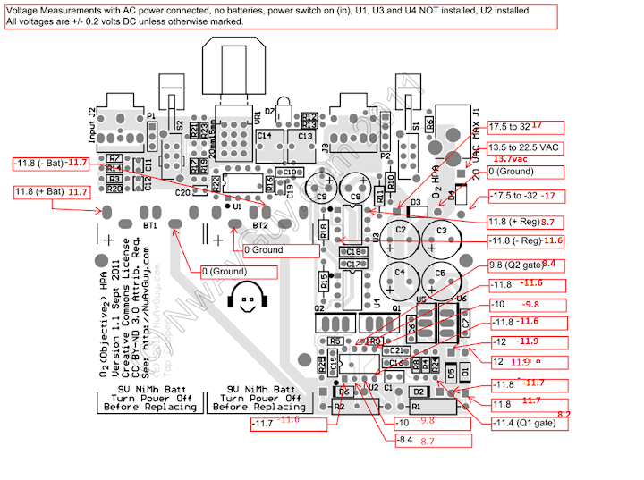
I just finished building my first o2 and I'm in the process of testing everything. The amp turns on and I get sound with no distortion or anything but I do get very loud turn on pop. I checked the troubleshooting info on the o2 website and it said to check the voltages of U2 which are fine, but I did notice u3 opamps positve voltage is low around 8.5v the negative rail is fine it's -11.65v. Also the voltage measured at r24(q1 gate) is reading 8.3v not -11.4. I'm reading through the trouble shooting guide but can't seem to figure out the problem. Any ideas? My ac adapter is 12v 200ma I tested it and it puts out about 14.2vac.
Last edited:
I think I've narrowed it down to a bad q1 not 100% sure just yet I'm gonna do some more testing and see what I find.
what could be the cause of the volume control not working? I'm hearing only the slightest level of signal with music on and the pot making rustle noises when turned.
opamp voltages all seem in order ( I'm running the amp on batteries currently and the numbers are apprixmately 70% of AC operation) and i've desoldered the pot and it meausres fine it seems- 9.71kohm in both channels...
any advice is very appreciated.
That pot should be silent when turning, noise indicates DC across the pot. Check for DC at the input to the pot. I don't have a schematic in front of me (I could swear I have one on this computer somewhere) but check the circuit ahead of the volume control for DC offset. Is there any DC offset on the output?
As for level: what you really want to do is supply a sine wave input signal (say 400Hz or thereabouts) and trace it with your meter on ACV from input to the volume pot, see where it disappears. You should be able to generate or download a signal like that from a variety of sources.
@nezbleu, I stand corrected. For some reason I thought this was considered okay for the O2. In fact, it's something RS specifically designed against. I'll have to be more careful in the future. Sorry for mixing messages, guys.
Yesterday was not too lucky day.
Finally I received my O2 kit. Arranged parts and start to building amp. Slowly and with taste and enjoying🙂
After few hours all solder jobs are ready, all come out perfect, nice lucking board.
I have not suitable transformer yet, so I insert 2 fully charged batterys and push power switch. LED start to shine, so far so good.
Then I take my multimeter to make some checks. I start with output DC, connect crocodile to output jack's ground pin and with probe touch one channel's output.
In this moment with loud bang exploded LED. Naturally. Half of red plastic are gone, inside electrodes are visible.
I am not sure, maybe I touch something with probe, maybe short output. However shorting headphone amp for a second is normal, putting phone jack in and out we do it every time. Maybe it is only coincidence, LED was defective or something else.
Any ideas?
Today I ordered new LEDs and to be sure FETs too from Farnell. Let's see tomorrow🙂
Farnell have not original LEDs, so I ordered BOM's recomended replacement part Avago HLMP-1301
HLMP-1301 - AVAGO TECHNOLOGIES - LED, 3MM, HE-RED | Farnell Latvijas Republika
In O2 description he say, most important are LED's forward current and forward voltage, so I ordered this two LEDs too, just because of colour:
HLMP-1401 - AVAGO TECHNOLOGIES - LED, 3MM, YELLOW | Farnell Latvijas Republika
HLMP-K401 - AVAGO TECHNOLOGIES - LED, 3MM, ORANGE | Farnell Latvijas Republika
Anyone deeper in power part design, can I use this LEDs? Of course, proper working amp is more important then LED's colour. What happens if forward voltage is little bit higher or lower?
And any ideas what was happen with my amp?
Last edited:
...connect crocodile to output jack's ground pin...
The two PC board traces feeding the LED run between the output jack ground pin and the edge of the PC board. If you hold the PC board upright facing the front, and then flip it over, that little round via hole to the left and slightly up toward the edge of the PC board from the output jack ground pin goes to the anode of the LED. When you connected your crocodile clip to the output jack ground pin it may have accidentally touched that metal via hole. That would put 9 volts right across the LED and probably cause it to pop.
If that is what happened the LED is probably the only casualty, but there is a small chance U2 would get nailed too. If that isn't what happened then make sure U2 is in the right way. The little dot on the top should be facing the batteries.
A better place to connect your meter for ground is the metal shell of the gain switch or one of the two holes of P2 closest to the PCB board edge. When checking DC output offset I use a 3.5mm stereo plug with the cover unscrewed (no wires attached) so I can easily clip onto the 3 connections.
Last edited:
I got back to testing my O2 today I double and triple checked all my voltages reflowed a few suspect solder joints and now it's working perfectly no turn on pop at all and it sounds great.


Last edited:
I think I may have spoke to soon I'm getting the turn on pop again and my power supply is unbalanced. It looks like the problem is the Q1 mosfet but id like to be sure before I spend any money ordering more parts. Any help would be greatly appreciated. Thanks

- Home
- Amplifiers
- Headphone Systems
- The Objective2 (O2) Headphone Amp DIY Project