Well, I was thinking that the cone of the coax would act as a waveguide/horn for each of the coax tweeters, effectively making the radiating surface as big as the cone. But you guys have far far more experience with arrays than I, so I will accept your explanation. Thanks!NC535 is correct; even with coaxials, the spacing of the tweeter is the deal-breaker.
j.
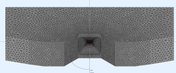
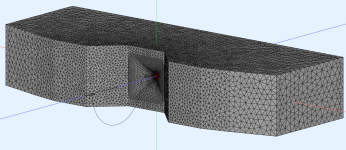
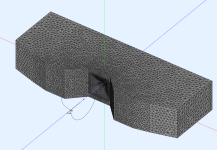
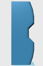
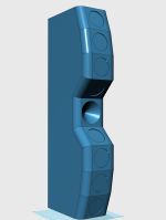
Here's an enclosure and waveguide I'm working on.
As usual, I'm using the shape of the enclosure to change the wavefront shape. The way that it works is like this: https://www.diyaudio.com/community/threads/loudspeaker-enclosures-are-waveguides.363630/
Attached are some pics of the enclosure modeled in 3D, and what it looks like in Abec.
Here's the model that you can simulate using ATH and ABEC.
Spoiler alert: before you bother modeling this, it doesn't work well. I am posting it because maybe it will save someone the trouble of finding out the hard way 🙂
; -------------------------------------------------------
; Pula Waveguide
; -------------------------------------------------------
Throat.Diameter = 25.4 ; [mm]
Throat.Angle = 17.5 ; [deg]
Throat.Profile = 1
Slot.Length = 12.7 * cos(2*p)^4
Length = 50.8 ; [mm]
Coverage.Angle = 45
Term.s = 0.8
Term.n = 3.7
Term.q = 0.995
Morph.TargetShape = 1
Morph.FixedPart = 0.25
Morph.Rate = 3
Morph.TargetWidth = 150
Morph.TargetHeight = 150
Morph.CornerRadius = 25 ; [mm]
Source.Shape = 1
Source.Curv = 0
Source.Radius = -1
Source.Velocity = 1
; -------------------------------------------------------
; Mesh Setting
; -------------------------------------------------------
pula_enclosure = {
point P0 76.2 0 10
point P1 171.66 -95.46 12
point P2 306.66 -95.46 14
point P3 406.4 -72.02 20
point P4 566.47 -25.84 25
point P5 566.47 310.94 25
point PB 0 310.94 25
line P0 P1
line P1 P2
line P2 P3
line P3 P4
line P4 P5
line P5 PB
}
Mesh.Enclosure = {
Plan = pula_enclosure
Spacing = 5,25,5,25
;Depth = 200
;EdgeRadius = 25
;EdgeType = 1
;FrontResolution = 8,8,16,16
;BackResolution = 20,20,20,20
}
Mesh.AngularSegments = 32
Mesh.LengthSegments = 25
Mesh.SubdomainSlices =
;Mesh.InterfaceOffset = 8.0
Mesh.Quadrants = 1
Mesh.ThroatResolution = 4
Mesh.MouthResolution = 8
ABEC.SimType = 2
ABEC.f1 = 625; [Hz]
ABEC.f2 = 10000; [Hz]
ABEC.NumFrequencies = 49
ABEC.MeshFrequency = 1000 ; [Hz]
ABEC.Polars:SPL_H = {
MapAngleRange = 0,90,19
Distance = 3 ; [m]
Offset = 200
}
ABEC.Polars:SPL_V = {
MapAngleRange = 0,180,37
Distance = 3 ; [m]
Offset = 200
Inclination = 90
}
Output.ABECProject = 1
Output.STL = 1
Report = {
PolarData = "SPL_H"
Title = "Pula waveguide - Horizontal 20"
Width = 2880
Height = 1620
;MaxAngle = 0
NormAngle = 20
}
Attachments
-
 Screenshot 2025-05-10 133542.png1.3 MB · Views: 33
 -
 Screenshot 2025-05-10 133512.png1.1 MB · Views: 31
 -
 Screenshot 2025-05-10 133447.png993.2 KB · Views: 31
 -
 Screenshot 2025-05-10 133418.png132.7 KB · Views: 38
 -
 Screenshot 2025-05-10 133402.png104.1 KB · Views: 35
 -
 Screenshot 2025-05-10 133347.png176.4 KB · Views: 33

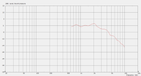
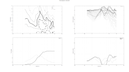
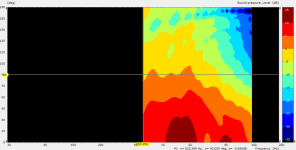
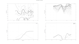
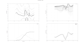
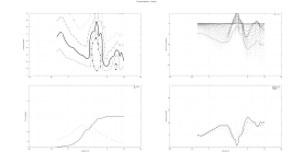
Here's some simulations of the waveguide and enclosure from my last post.
As noted, they're comically bad, but maybe it will save someone from trying it.
If anyone is wondering what I was attempting, my idea was that the angled part of the enclosure, above and below the waveguide, would allow the waveguide to control directivity to a lower frequency. Similar to a conventional waveguide with the left and right side cut off, leaving the center 'slice' alone.
The attached sims are:
1) vertical and horizontal directivity maps
2) vertical and horizontal on-axis frequency response
3) The vertical and horizontal reports produced via ath. These are normalized at zero and twenty degrees.
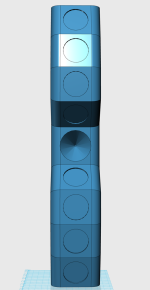
Something to note, is that the "vertical" and "horizontal" are swapped. This is admittedly confusing. The reason this is, is because the User-Defined Enclosure plan in ATH basically "extrudes" a two dimensional shape.
Similar to this:

As noted, they're comically bad, but maybe it will save someone from trying it.
If anyone is wondering what I was attempting, my idea was that the angled part of the enclosure, above and below the waveguide, would allow the waveguide to control directivity to a lower frequency. Similar to a conventional waveguide with the left and right side cut off, leaving the center 'slice' alone.
The attached sims are:
1) vertical and horizontal directivity maps
2) vertical and horizontal on-axis frequency response
3) The vertical and horizontal reports produced via ath. These are normalized at zero and twenty degrees.
Something to note, is that the "vertical" and "horizontal" are swapped. This is admittedly confusing. The reason this is, is because the User-Defined Enclosure plan in ATH basically "extrudes" a two dimensional shape.
Similar to this:
Attachments
-
 Screenshot 2025-05-10 165344.png61.4 KB · Views: 28
 -
 050725-pula_04-horizontal0.png364.1 KB · Views: 24
 -
 Screenshot 2025-05-10 165330.png61.9 KB · Views: 26
 -
 Screenshot 2025-05-10 165319.png110.6 KB · Views: 29
 -
 Screenshot 2025-05-10 165306.png148 KB · Views: 27
 -
 050725-pula_04-horizontal20.png360.4 KB · Views: 25
 -
 050725-pula_04-vertical20.png337.8 KB · Views: 28
 -
 050725-pula_04-vertical0.png354.6 KB · Views: 29