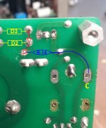
Just for my own curiosity, what direction is the current flowing (if that makes sense) in the relay? From the end closest to the LED (A/B/C) toward the Qs or vice verse. I would assume from the transistors toward the relay ...
For the relay to turn on, Q1 BC639 turns on and its collector goes almost to ground potential, thus pulling terminal A of the relay almost to ground potential (say ~0.3V). Terminal C is at the same potential as the power supply to the protection circuit, nominally +24V (could vary a lot depending on trafo voltages, R14, etc.). Hence current flows into terminal C of the relay, through the relay coil, out of terminal A, into collector of Q1, through Q1, and out of the emitter of Q1 to ground.
Great - can you also describe the function of D2 & D3? Is everything coming off the diodes (DR1-2-3-4) converted from +/- 35 VDC to +24V by D2 & D3 and passed through R14 to terminal C of the relay?
Or is all the voltage reduction simply the function of R14?
Or is all the voltage reduction simply the function of R14?
Attachments
Great - can you also describe the function of D2 & D3? Is everything coming off the diodes (DR1-2-3-4) converted from +/- 35 VDC to +24V by D2 & D3 and passed through R14 to terminal C of the relay?
D2 & D3 are a full-wave rectifier that generate a rectified signal with a peak value of about 35V. That's filtered by R14/C14 to give a DC supply for the protection circuit with a small ripple. R14 also serves to limit the current through the relay coil when it's pulled on - the peak value is about (35V/(relay coil DC resistance + R14)) - it cannot exceed about 200 mA even if the relay coil is shorted out, and in normal operation with a good coil it will be significantly lower than that.
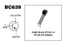
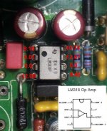
Regarding Q1, the B-C and the B-E junctions should show forward-biased diode conductivity with a DMM - something like 400 to 600 ohms in the 2k range. Check each junction with DMM leads (red & black) in both directions.
Latest results 😡
Both BC639s allow proper operation on the good module.
Neither allows proper operation on the bad module.
Swapping R14 from the good module to the bad - no ckick.
Same R14 back in good module works fine.
Confirmed 35V from R14 to pin B on the relay.
Also on the relays (tested three) - I didn't get confirmation that being able to activate them with 18.5 VDC across pins A and C out of circuit is enough to insure they will function properly in the circuit. Is that correct?
Both LM318s work in the good module.
Confirmed continuity from all LM3886 pins (at junction to chip body) to their next component in the circuit. I used a new LM3886 and not one that had been pulled.
Removed all flush/blind mounted caps and inspected for solder bridges.
Re-flowed every pad on the bottom of the board.
Liberal alcohol wash and power air blasting of top of the PCB.
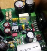
C32 is the only place where sockets remain. I replaced those and also confirmed both of those specialty caps work in the good module. The good module activates the relay - and lights the LED even without C32 populated.
I looked for the following information but couldn't find a reference. Can someone supply the correct voltages on these two components? Also please confirm that all those readings can be taken with the negative probe at PGND. I'm always a bit concerned about using the wrong ground reference - signal vs. power.😱
If I can not confirm correct voltages on those two components the last step is getting and new board. That feel like ignominious defeat -- but I'm out of ideas.
  😕
😕
EDIT: The only thing mentioned that I haven't done is comparative readings on all the resistors. Siva, do you have a silkscreen of the top of the V1.3? It would make that step much easier to do and to post the results.
Both BC639s allow proper operation on the good module.
Neither allows proper operation on the bad module.
Swapping R14 from the good module to the bad - no ckick.
Same R14 back in good module works fine.
Confirmed 35V from R14 to pin B on the relay.
Also on the relays (tested three) - I didn't get confirmation that being able to activate them with 18.5 VDC across pins A and C out of circuit is enough to insure they will function properly in the circuit. Is that correct?
Both LM318s work in the good module.
Confirmed continuity from all LM3886 pins (at junction to chip body) to their next component in the circuit. I used a new LM3886 and not one that had been pulled.
Removed all flush/blind mounted caps and inspected for solder bridges.
Re-flowed every pad on the bottom of the board.
Liberal alcohol wash and power air blasting of top of the PCB.
C32 is the only place where sockets remain. I replaced those and also confirmed both of those specialty caps work in the good module. The good module activates the relay - and lights the LED even without C32 populated.
I looked for the following information but couldn't find a reference. Can someone supply the correct voltages on these two components? Also please confirm that all those readings can be taken with the negative probe at PGND. I'm always a bit concerned about using the wrong ground reference - signal vs. power.😱
If I can not confirm correct voltages on those two components the last step is getting and new board. That feel like ignominious defeat
-- but I'm out of ideas. 😕EDIT: The only thing mentioned that I haven't done is comparative readings on all the resistors. Siva, do you have a silkscreen of the top of the V1.3? It would make that step much easier to do and to post the results.
Attachments
Last edited:
Siva, do you have a silkscreen of the top of the V1.3? It would make that step much easier to do and to post the results.
You have checked whether R11 is 1 ohm or open, right? Open R11 is the most common failure on these boards, usually due to some kind of grounding error or trafo connection error. None of the other resistors is likely to fail, in my experience.
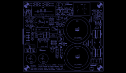
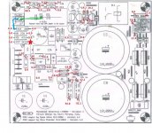
Here's the image of the silkscreen layer of the V1.3 - it's a bit difficult to view since I pulled it straight off the gerber .plc file using gerbv - you can probably enlarge or convert to a .jpg to view it better as needed.
Edit: These may or may not be issues, but I noticed the following:
1) C4 (0.15 uF/100V Wima MKP4) looks a bit chewed up on one corner, possibly due to contact with a soldering iron?
2) R1 and R4 are in contact with each other - try moving them a millimeter or so apart, just a slight air gap is needed.
3) A bit of flux or something on R11.
Attachments
Last edited:
O.K. - thanks bunches. I have to go out for personal business but will pick up again later in the day.
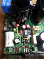
Well, If I wasn't thoroughly confused before - I am now. I would have expected the readings almost opposite of what they show. I did as much double checking as possible and believe this is accurate.
What was really interesting - on the good module - is just touching the starred end of R-37 with the positive probe opens the relay momentarily. Could not get a live reading as a result.
I did add a source and a speaker to the good module to confirm proper operation - works great.
Siva, hope you can see a picture here. 🙄 (Found an original document from your kit package 😀)
Attachments

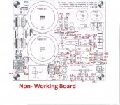
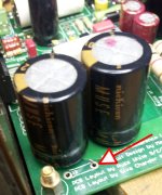
Looks like R11 is open. See voltage over R11. Its only 1 Ohm. This causes a large offset at the output preventing the relais from activating. Maybe there is something else causing R11 to break.
Yup, R11 is open - which is most probably the cause of lots of other things being stuck near -Vs, thus causing the speaker protect circuitry to leave the relay contact off (i.e. in protect). Replace R11 with a known good 0.5W resistor in the range of 0.5 to 4.7 ohms for testing, and see if the relay fires.
If R11 fails again immediately, then there are other problems to debug.
If R11 fails again immediately, then there are other problems to debug.
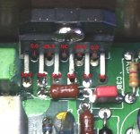
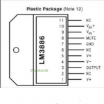
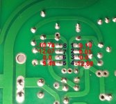
Try adding some solder to pins 4, 7 and 8 of LM3886. pin 4 should be -34V and I think pin 8 should be -7V
Sorry 😱, I got some of the readings turned around. This is what I actually have. While following the traces I did find that rare thing where one lead had broken from R2. Replaced it with new 1/4 W 10K resistor but no change. That trace does lead to pin 8 (mute) - should there be voltage there in un-muted state after the relay avtivates?
Attachments

The mute voltage at pin 8 is independent of the relais. no voltage is mute!!!! All looks good at the LM3886.
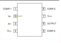
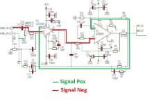
Can you measure audio signals at pins 2,3 and 6 of LM318 with audio connected to conn1. First check schematic confirming pin numbers and understanding of what you are measuring.
Can you measure audio signals at pins 2,3 and 6 of LM318 with audio connected to conn1. First check schematic confirming pin numbers and understanding of what you are measuring.

Can't tell if your measuring low DC voltage or audio. Try using a cheap headphone in series with a 20uF 50V capacitor to trace the audio signal.
The voltages at pins 1, 5 and 8 look wrong. Probably enough to conclude that the LM318 is the problem.
The voltages at pins 1, 5 and 8 look wrong. Probably enough to conclude that the LM318 is the problem.
The readings in post #1826 were done with the same connection to PGND as the previous posts. Should I use signal ground for any readings on LM318?
I just did a full swap and both LM318s function properly in the good module. Neither makes any change on the bad build.
Should I do the earphone test with the amp powered on - off or both. I confirmed the earphone signal at pcb input, but the closest cap I have is 22uF/25. Is that O.K.? These are 20 year old PC phones (have several) so if I loose them by not having the cap - no big deal.
Yes Joseph - that's what it reads and is also the pin that cycles the relay when it is touched with the positive probe - both modules.
Attachments
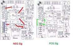
Before I start poking around - I can see the negative signal path, not so much with the positive.
If I attach the earphone signal ground to the input signal ground pad on the board - which points do I probe with the earphone live signal probe?
BTW: My attitude?? - Not so much frustration, but more like a good learning experience - combined with something like finding those last few pieces in the family Christmas jigsaw puzzle on the dining room table. No Egg Nog till...... 😀 🙄 😀
Attachments
Last edited:
- Home
- Amplifiers
- Chip Amps
- The new "My Ref" Rev C thread