The closest I have is 150R/.5W. Will that work?
BTW, Last time I was in my local Radio Shack the Regional Manager was there. I let loose on him for not supporting the DIY community anymore. Stocking resistors larger than 1/2 watt was one of the things I complained about. He said they are hearing the same thing worldwide and are planning to make some major adjustments soon. So there is hope. 😉
I did pick up one of their new "Electric Paint" pens for PCB repairs but haven't used it yet.
Bare Conductive
Last edited:
Thanks Mr.T - same problem, All RS 360 are online only.
Latest attempts:
150R 1/2 W = no change
270R 1/2 W = no change
With both of those there is no LED or relay activity at all with the verified good LM318 installed. Mounting the LF0-1 returned the flash and click at power down - after ~ 2 seconds. The mystery continues.😕
Siva, just in case, do you have any V1.3 boards left?
Is it simply a relay problem?
Do you have continuity across the relay when the circuit is powered?
Can you temporarily short across the relay NO contacts to check Audio Circuit operation?
Do you have continuity across the relay when the circuit is powered?
Can you temporarily short across the relay NO contacts to check Audio Circuit operation?
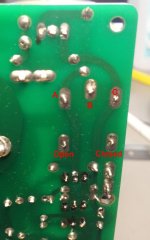
The relay seems to be good, since it clicks occasionally. This is probably a short or open circuit or dry solder joint, since it was working fine earlier. However, go ahead and do an unpowered static in-circuit measurement/comparison with the known good board, on all resistors at least. Also check that the LM3886 'mute' signal trace near the front edge of the PCB is not coming into contact with the heatsink. 150 ohms should be OK for R14, but seems to be unrelated to the problem.
V1.3 boards are still available as a last resort, no problem.
V1.3 boards are still available as a last resort, no problem.
Unfortunately, the few values that show up on an underpowered probe are all the same on both boards.
Several resistors flash a value and immediately bump to 0.0. There were a few that fluctuated wildly till I used the bulb tester to drain the caps as best I could. There is still a residual of 0.04 mV on one side and 0.07 on the other - both boards. Don't know if it's possible to pull those down to zero, but the fluctuations no longer appear.
I will most likely short something due to the close proximity of some parts, but should I attempt a full board sweep with power?


Guess I could do a mark-up on the bottom with a felt tip pen and avoid the shorting potential. Siva, still need those docs if you can track them down.
I did do another reheat pass on the non-functioning build but that made no improvement.
Several resistors flash a value and immediately bump to 0.0. There were a few that fluctuated wildly till I used the bulb tester to drain the caps as best I could. There is still a residual of 0.04 mV on one side and 0.07 on the other - both boards. Don't know if it's possible to pull those down to zero, but the fluctuations no longer appear.
I will most likely short something due to the close proximity of some parts, but should I attempt a full board sweep with power?
Guess I could do a mark-up on the bottom with a felt tip pen and avoid the shorting potential. Siva, still need those docs if you can track them down.
I did do another reheat pass on the non-functioning build but that made no improvement.
Last edited:
Unfortunately, the few values that show up on an underpowered probe are all the same on both boards.
Several resistors flash a value and immediately bump to 0.0.
What I meant was to remove power and all connections to both boards, allow the electrolytics to discharge fully (say 15 minutes) and measure all the resistors - just as a sanity check to ensure that both boards have similar static resistances and nothing has shorted/opened.
If there are significant differences in some resistance values, the debugging can proceed from there.
Hey Siva, I believe that's what I did - except added the "Bulb Flush" as an extra measure. The boards sat un-powered overnight both Wednesday and Thursday evenings. Both times that occasional fluctuation on some resistors occurred. That's when I decided to try the bulb - and that problem stopped. I did measure EVERY resistor on both boards more than once, but couldn't find any differences (other than the mis-match at R14).
I ordered new pairs of 180R, 220R and 470R at 1Watt. They should arrive this afternoon or in the morning.
EDIT: I think it might be significant to your intent that both boards had the identical residual readings on the ac in pins after the bulb tester drain. Correct ?
I ordered new pairs of 180R, 220R and 470R at 1Watt. They should arrive this afternoon or in the morning.
EDIT: I think it might be significant to your intent that both boards had the identical residual readings on the ac in pins after the bulb tester drain. Correct ?
Last edited:
yesterday, I was compare the MyRef Rev C amp with classic class D amp using TDA7492 and change with Tripath. in my hearing, i cannot choose which one sound better. Just the power difference. the MyRef Rev C have a much bigger power. The details in low, mid, and high, at the same volume, I can tell both amp sound 99% same. I use laptop 3.5mm output connected directly to amp and then amp to 2 way speaker with 84db sensitivity. tweeter using soft dome, and bass with kind of kevlar. The right speaker I test with MyRef, and the left speaker with class D amp (sometime I switch with Tripath)
I would like to ask you all that already successfully build MyRef, how do you compare the sound? please share, what kind of speaker do you use, and also your setup.
I dont know why. I playing instrument, country, jazz, and slow pop rock, all is from CD, I convert to my laptop to flac file. but my hearing feels same for both amp. maybe my speaker is too bad. please suggest me the easiest way how to test the difference.
I use laptop 3.5mm output connected directly to amp and then amp to 2 way speaker with 84db sensitivity...
Internal laptop sound chips aren't too great - they're only meant to drive typical internal speakers (~1") and earbuds. You may not be able to differentiate between a MyRef and Tripath with a laptop source.
Use a dedicated CD player as the source, the differences will be immediately apparent in most cases.
I'm a firm believer that one can't really hear what the MyRefs are capable of without some pretty good speakers. I don't mean expensive necessarily, but some that are designed for critical listening as opposed to just general entertainment. My favorite quip on the MRs is "You don't know what you got till it's gone". When the distortions and coloration is removed the music shines through. These amps excel at refinement and detail. If one is looking for "Party Sound" they may not be the best choice - though certainly capable of filling the room.
It seems everything always comes down to what we want to invest, but if the budget doesn't allow, at least try to hear them on a quality set of speakers even if that means temporary use of someone else's set.
My personal view is at least a 5.5" to 6" woofer is a minimum to judge the quality and performance at the low end. 8" and larger also work well and don't appear to put a strain on headroom. With the great imaging the MRs can produce, I think using different amps per speaker prevents a listener from experiencing one of the best features of the amps, Try to listen in stereo when possible.
Last edited:
Use a dedicated CD player as the source, the differences will be immediately apparent in most cases.
how about DAC? maybe 24 bit 96KHz or 192KHz? is it enough ?
if enough, please suggest one of DAC which you ever test and recommended to buy.
if not, what do you prefer with SACD player or CD player. I dont know whith the SACD, is it totally different format compare to usual audio CD ? please also suggest the cd player.
I agree with Bob M, two open sounding amps which don't have distortion issues wont sound that different when running them the way you have described. Above a certain level of quality, amps don't sound vastly different at low power anyway. Speakers make the biggest difference, a good quality set (not necessarily hugely expensive) is needed to get the best results from a good amp and source.
DAC - depends on your budget. If you don't have much money to spend maybe build a kit. If you don't want to do that, Musical Fidelity's V-DAC is very good for the money. You can add improvements as and when you can afford them like an upgrade power supply and maybe a V-LINK. A higher budget opens up loads of choice, as usual.
DAC - depends on your budget. If you don't have much money to spend maybe build a kit. If you don't want to do that, Musical Fidelity's V-DAC is very good for the money. You can add improvements as and when you can afford them like an upgrade power supply and maybe a V-LINK. A higher budget opens up loads of choice, as usual.
if enough, please suggest one of DAC which you ever test and recommended to buy.
... please also suggest the cd player.
For the DAC, I use a HifiMeDIY 24/96 TE7022 + ES9023 USB-only DAC with a notebook. I have the older UAE23 v1.1, which I have modified a bit. The current version uses a different USB to I2S chip, a Savitech SA9023, which is apparently just as good or better.
For the CD player, I have a modified Kenwood DP-1001, modified Marantz CD-4000, and several others. I'd recommend the CD-4000 or its alter ego, the Philips CD-723/753.
Hello,
K75 and FT-1 are now here 🙂
The K75 are quite big, I don't know how I will fit them, maybe I will try to cut the heatsink just to have enough place for the cap.
If someone here would like to try just two K75 in Rev C or Freeman Edition send me a MP 😉
K75 and FT-1 are now here 🙂
The K75 are quite big, I don't know how I will fit them, maybe I will try to cut the heatsink just to have enough place for the cap.
If someone here would like to try just two K75 in Rev C or Freeman Edition send me a MP 😉
Attachments
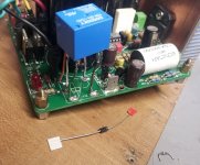
Picked up on trouble shooting my problem V1.3. My focus was on the relay and there were some lifted pads, so I used pigtails to insure continuity from trace to relay pin. Also confirmed relay operation by using a 18.5 VDC wall wart - works as it should.
Next in line would be the source of the current to power the relay. While checking the production rev schematic i see that D4 is called out as 1N4001 - and the BOM I have lists SBYV27-100-E3/4. I have a new 1N4001 but don't know if I should try it.
Also, where can I check for the correct current intended to feed that diode and/or the relay coil. Is it just negative probe to PGND and the two sides of D4?
Attachments
Next in line would be the source of the current to power the relay. While checking the production rev schematic i see that D4 is called out as 1N4001 - and the BOM I have lists SBYV27-100-E3/4. I have a new 1N4001 but don't know if I should try it.
Also, where can I check for the correct current intended to feed that diode and/or the relay coil. Is it just negative probe to PGND and the two sides of D4?
I haven't encountered any failures in the DC protect circuit or the relay itself, though of course, dry/cracked solder joints, solder bridges and open circuits can happen anywhere.
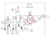
The diode is just a flyback diode to protect the BC639 relay coil driver transistor when the relay turns off. Anything rated at over 50V reverse blocking should be fine, i.e. just about any diode. IIRC, I have supplied 1n4001 to 1n4006, as also UF4007 in some kits.
The current through the relay is a function of the relay DC impedance and the voltage across it. I don't have the DC impedance spec for the Goodsky relay in front of me, but the relay drive current has never been a problem with the validated R14=180R and R21=100K in my BoM.
If in doubt about the relay drive circuit, replace Q1, BC639 and measure the removed BC639 with a multimeter across B-C and B-E junctions, as well as C-E. I haven't ever seen a failed BC639, but it could happen on rare occasions.
I'd be more inclined to check the DC output offset voltage at the speaker out terminal wrt to PGND - anything below about 100 mV is fine, but it's usually below 10..20 mV in most cases.
Last edited:
Thanks Siva, Those are thorough explanations. The new 1N4001 didn't help. I believe Q1-2-3 are good as yesterday I cross mounted them one at a time and the results were consistent - they all worked on the good module and none made any change on the non-functioning board. However I will check the BC639s out of circuit just to be sure. I did a similar check on some IRFP240 mosfets for a discrete amp so it sounds somewhat familiar. Am I looking for a closed/shorted set among those various pin pairs or a resistance value.
Just for my own curiosity, what direction is the current flowing (if that makes sense) in the relay? From the end closest to the LED (A/B/C) toward the Qs or vice verse. I would assume from the transistors toward the relay, but the location and function of R14, D2 and D3 seems to suggest otherwise. Sorry, I'm obviously not an amp designer.😱
Just for my own curiosity, what direction is the current flowing (if that makes sense) in the relay? From the end closest to the LED (A/B/C) toward the Qs or vice verse. I would assume from the transistors toward the relay, but the location and function of R14, D2 and D3 seems to suggest otherwise. Sorry, I'm obviously not an amp designer.😱
Attachments

Last edited:
- Home
- Amplifiers
- Chip Amps
- The new "My Ref" Rev C thread