Thanks Troy, the mu metal band is a little bit cheaper than copper wrap so if there's no advantage in using copper screening, i'll probably go for the mu banded version.
Mu metal band sounds like the sort of name a German hard rock group might go for 😀
Mu metal band sounds like the sort of name a German hard rock group might go for 😀
Hello,
I have a My-ref A... and I would like to try the rev C. I have a question about the value of R41. In the Penasa's REV C schematic I have found that R41,42 are 47ohm... but elsewhere I have found a different value, 270 ohm. So which is the right one ?
thanks !
marco
PS: in the FE there is no R41,42...
Last edited:
I have a question about the value of R41. In the Penasa's REV C schematic I have found that R41,42 are 47ohm... but elsewhere I have found a different value, 270 ohm. So which is the right one ?
All of them...
270R was the intial Rev C value, next Mauro stated that it can be lowered it to 47R or omitted at all (like in the FE)
Just finished chasing down a hum problem. It turned out to be a combination of the terminal blocks I was using and the fact that the signal pin inside the RCA could break contact. Part of the solution was to solder the input leads directly to the board - something I had planned to do eventually.
So to Dario - those holes are quit small IMHO, so I'm sure you have experimented with several wire types and sizes. Do you have a suggestion for the beat of the best at that location - RCA to PCB?
So to Dario - those holes are quit small IMHO, so I'm sure you have experimented with several wire types and sizes. Do you have a suggestion for the beat of the best at that location - RCA to PCB?
That's what I have. Been using his silver coated Teflon stuff for all my builds. Just thought D might have something he likes a lot 😉
P.S. His multi-color multi-size heat shrink package really comes in handy.
P.S. His multi-color multi-size heat shrink package really comes in handy.
Last edited:
All of them...
270R was the intial Rev C value, next Mauro stated that it can be lowered it to 47R or omitted at all (like in the FE)
Thank you Dario 😉
I have some metal resistor of 147 and 270 ohm, otherwise I have some SMD1206: 10, 23, 47 and 69 ohm...
I think I will try with SMD 47 ohm.
Ciao !
That's what I have. Been using his silver coated Teflon stuff for all my builds. Just thought D might have something he likes a lot 😉
P.S. His multi-color multi-size heat shrink package really comes in handy.
What I like best is in fact the multisize heat shrink package...
Also really nice is the "TFT Teflon 6N Copper Wire Cable" you can find on ebay.
This long grain copper cable has different strand sizes like Kimber cables.
Sadly both are directional and for optimal results you should test them for direction... 😉
This cable is very good for internal signal wiring in preamp's, I use it when i need a decent quality miniature twisted screened pair - VanDamme 278-401-000 Cable, , Violet Sheath from Conrad Electronic UK
I find that my heatsink is still warm when no music played with rca plugged into laptop, and I can't feel the heat difference when playing low volume. is it normal?
Hello,
I am sorry if I am off topic ... 🙄 but I have soldered the components to change My-ref A in My-ref C in that way:
I don't have yet turn on the amp, do you think it is right ?
I have used SMD where it was possible to solder them, here is a picture:
I am sorry if I am off topic ... 🙄 but I have soldered the components to change My-ref A in My-ref C in that way:
An externally hosted image should be here but it was not working when we last tested it.
An externally hosted image should be here but it was not working when we last tested it.
I don't have yet turn on the amp, do you think it is right ?
I have used SMD where it was possible to solder them, here is a picture:
An externally hosted image should be here but it was not working when we last tested it.
An externally hosted image should be here but it was not working when we last tested it.
Last edited:
I don't have yet turn on the amp, do you think it is right ?
At first glance, yes, it seem right.
At first glance, yes, it seem right.
It's now playing 😀
I don't know if I prefer the A or C version... but, ok, I've listen only 2 songs 😱 The high frequencies are more defined...
Thanks Dario !
There is a problem, I have a hum 😡
The first time I turn on the amp I didn't hear any noise, I listen to music for about an hour.
The day after when I power on the amp, I hear the hum. I am not sure that the first time the the amp was silent... but I didn't notice any noise.
Anyway, the the "A" version has run for two years without any noise, totally silent.
The amp is not in a metal box, it just lay in a wood table...
The body of the pot is connected to the cold (signal).
The GND (PCB) is connected to the GND (IEC) by a 47 ohm resistor.
The body of the selector is not connected to the cold pole.
If I move the wires there is no change in hum noise.
I know that a metal box is better... but it has run silently for more than two years
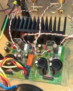
I have also change C29 and C13, the new capacitor (SCR MKP) is a bit bigger than the old one and now C13 is touching C9 and C15...
Here is a pic :
Any ideas to solve this hum ??
The first time I turn on the amp I didn't hear any noise, I listen to music for about an hour.
The day after when I power on the amp, I hear the hum. I am not sure that the first time the the amp was silent... but I didn't notice any noise.
Anyway, the the "A" version has run for two years without any noise, totally silent.
The amp is not in a metal box, it just lay in a wood table...
The body of the pot is connected to the cold (signal).
The GND (PCB) is connected to the GND (IEC) by a 47 ohm resistor.
The body of the selector is not connected to the cold pole.
If I move the wires there is no change in hum noise.
I know that a metal box is better... but it has run silently for more than two years
I have also change C29 and C13, the new capacitor (SCR MKP) is a bit bigger than the old one and now C13 is touching C9 and C15...
Here is a pic :
An externally hosted image should be here but it was not working when we last tested it.
Any ideas to solve this hum ??
Last edited:
You have quite large AREAs of loops at all the In/Out sockets.
Tighten these up, a lot.
The speaker outputs at the PCB have enormous loop AREAs.
You should look at using longer wiring and ensure the twist is kept for as long as possible right up until the twist reaches the PCB. Then make very short wires to the two tapping points. Keep the two untwisted wires very close to the PCB to minimise the loop areas between the PCB current and the wire current.
I somehow doubt this will cure the hum, but it might reduce it.
I suspect you have changed something else.
What did you change? See the brown wire of the right hand pair and that it passes directly along the top of the left hand white capacitor ! That is really asking the current in that speaker wire to affect the current in the capacitor.
You have quite large AREAs of loops at all the In/Out sockets.
Tighten these up, a lot.
The speaker outputs at the PCB have enormous loop AREAs.
You should look at using longer wiring and ensure the twist is kept for as long as possible right up until the twist reaches the PCB. Then make very short wires to the two tapping points. Keep the two untwisted wires very close to the PCB to minimise the loop areas between the PCB current and the wire current.
I somehow doubt this will cure the hum, but it might reduce it.
I suspect you have changed something else.
What did you change? See the brown wire of the right hand pair and that it passes directly along the top of the left hand white capacitor ! That is really asking the current in that speaker wire to affect the current in the capacitor.
Thank you Andrew,
I have tried to rewire the IN/OUT and roll-back C13-29 to original capacitor but the noise is still there. I can "feel" the hum if I touch with my hand the woofer, it's quite loud and annoying 🙁
I have also bypassed the input selector but no improvement.
The original and silent version was: My-ref A + passive pot (10k). Then I have modified the circuit as you can see in photos above, replaced C13-29 with new cap and added input selector.
So... I suspect that I should roll back to A version 🙁 The PCB is intended for A version, maybe there is something wrong in new components placement. Any idea ?
marco
Attachments
I roll back to A version and it is terribly silent. That's nice but...
Does it make sens to try to use normal metal film resistor instead of SMD ? juste to keep the "track" more distant from PCB tracks?
Does it make sens to try to use normal metal film resistor instead of SMD ? juste to keep the "track" more distant from PCB tracks?
Last edited:
- Home
- Amplifiers
- Chip Amps
- The new "My Ref" Rev C thread