Apart from the heatsinks, there is little difference in cost between the F5 and the MyRef. In fact, the F5 has fewer components than the MyRef. Yes, it is probably more complex to setup. But after setup, it does not require any more tinkering. It can deliver up to 54W in class AB. Also, low voltage gain is a desirable property in a power amp in terms of noise.
This is no disrespect to the MyRef though. Mauro's design is unique and of course sounds wonderful in its own way.
This is no disrespect to the MyRef though. Mauro's design is unique and of course sounds wonderful in its own way.
umm... no, the F5 does 25W class A and then upto 54W class AB. As far as I know, the MyRef does about 40W. Anyway, I don't mean to start a war of words. This amp has some strong following. The F5 has its own set of followers and a thread that is 10,000+ strong and still going. Just wanted to say that it is worth finding out for yourself what the difference is between this amp and the F5. PCBs and transistor kits are readily available.
you forgot to specify the load impedance/resistance.umm... no, the F5 does 25W class A and then upto 54W class AB. As far as I know, the MyRef does about 40W. Anyway,
The F5 is a 25W into 8r0 ClassA amplifier.
It is also a 50W into 4r0 amplifier, but only the first 12.5W is in ClassA at this reduced load resistance.
The MyRef is 50W into 8r0 and also 50W into 4r0. But the PSU must be built/adjusted to suit the two different load resistances to get that maximum power capability for each.
Last edited:
With mention of the F5, I'm wondering about another possible "improvement" on the LM3886, forced Class A. I've seen Walt Jung do it with op-amps at the line level, but I don't recall such a mod on a power amp. It seems a 100mA current source or sink connected to the chip's output would make the "first watt" Class A, and not create too much extra heat.
Potentially the forced single ended ClassA operation of the output stage could/would make for a good ClassA amplifier of low output.
But one cannot release that potential because the front end circuit to which we have no access falls woefully short of the performance standards of what we would expect of a low power ClassA amplifier.
The ClassA version would certainly not make a good headphone amplifier.
But one cannot release that potential because the front end circuit to which we have no access falls woefully short of the performance standards of what we would expect of a low power ClassA amplifier.
The ClassA version would certainly not make a good headphone amplifier.
It sounded better than the class A I compared against. More detail, better image, similar depth, better bass control. Theoretically, the way it operates will deliver performance just as good as a class A.
Very interesting, If I understood well C9 should be increased to 725uF (or more) for c13=2.2uF and R13=100k?I use a formula that I found in this Forum which relates the input RC to the NFB RC to specifically limit the AC voltage across the NFB cap. The reason why we might want to do this is to minimise the distortion that the electrolytic will pass to the -IN amplifier terminal. Self and Cordell and many others tell us that the NFB cap will distort the amplifier output if it is made too small, i.e. develops significant AC voltage across it.
The formula that gives some meaning to Self and Cordell is
NFB cap >= sqrt(2) * Input cap * Rin / Rfeedback.
For the MyRefC 1uF would require >=362uF for Nfb cap
1u5F requires >=540uF and 2u2F requires >=725uF.
MyRefC has 220uF installed.
That's the theory behind the RC ratio and why .
I have been using input RC~90ms and NFB RC>=140ms for some years now and I have found it to sound good to my ears. It's nice when theory explains why it sounds good. It's even nicer when Theory allows one to predict the component values that might be close to optimum for good sound.
Now back to the input filters.
If you want the 0u68F to give extended bass response then increase Rin to 130k. RC = 88ms.
NFB cap >= 1.414 * 0.68 *100k / 390 >=247uF 220uF is probably close enough to satisfy the no AC voltage criteria for low distortion.
If you want to be sure that the NFB is not creating avoidable distortion then try increasing it to 330uF, or maybe even as high as 470uF
As an aside, I intend trying NFBcap = 220u//220u as an easy to carry out experiment on the effect it has on sound.
Last edited:
I have a strange newbie problem, which has mystified me a bit. When I first hooked up my rev c board I had no problem. I wired IEC 'input' earth or PE to a chassis post. I wired the transformer centre tap to that and ran another wire from the post to PGND on the board (but AC1/2 in the usual way). It's what I know as a chassis star ground and I've always done it this way in the past because it was something I was instructed to do on my very first amp build some 15 years ago.
Originally I didn't install CL-60 thermister or connect its associated safety ground solder pad to earth as I already had the power 0V line connected to PE in the method described. Anway I fired up, listened to it for a hour or so, no problem apart from hum coming from my active crossover which I expected. So far so good.
Now the tricky part. I later decided to add CL-60 to the board and run a safe earth wire from it's solder pad to the chassis earth post and attached the traffo centre tap directly to the PGND pcb lug as more usually done. AC1/2 connected as usual.
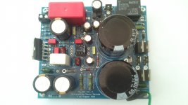
I powered up with amp still connected to the speaker (an oversight on my part). Immediately I started getting an intermittent loud crackling from the speaker, like someone scrunching up an empty crisp packet. Initially I thought there was a loose connection somewhere and started to investigate visually. Then after a couple of seconds SMOKE! From C1, (and possibly C2). I hit the mains power switch pretty damned pronto, let everything cool and discharge before disconnecting everything. Visual inpection reveals nothing I can see. No sign of burning on the pcb or C1/2 or anywhere for that matter.
I then connected my second board this time with no safety ground at all (yes I know) again no problem. So I'm mystified why the CL-60 to safety earth to PE method failed. Does anyone have any ideas what the problem is? Is it simply too much heat becuae of the CL-60, have I missed something or done something completely and utterly wrong?
BTW I was so bogged down in the original my ref c thread that I only came to the new thread a couple of days ago so didn't have the benefit of anyone's optimized BOM like Clave's. I can see immediately that my R1 and R4 (MOX) are mounted too close to the board and while I have 'em out would better be changed to carbon.
Lastly thanks to everyone for their excellent contributions getting me interested again albeit as an occasional hobbyist - I'm building a full range 3-way set of active speakers. It remains to be seen whether this amp is really the thing to drive the bass cone, tho I think the treble and mid is very good.
Addendum: I'm using a 0-22 0-20 80v/a toroidal fraffo - just for initial testing!
Originally I didn't install CL-60 thermister or connect its associated safety ground solder pad to earth as I already had the power 0V line connected to PE in the method described. Anway I fired up, listened to it for a hour or so, no problem apart from hum coming from my active crossover which I expected. So far so good.
Now the tricky part. I later decided to add CL-60 to the board and run a safe earth wire from it's solder pad to the chassis earth post and attached the traffo centre tap directly to the PGND pcb lug as more usually done. AC1/2 connected as usual.
I powered up with amp still connected to the speaker (an oversight on my part). Immediately I started getting an intermittent loud crackling from the speaker, like someone scrunching up an empty crisp packet. Initially I thought there was a loose connection somewhere and started to investigate visually. Then after a couple of seconds SMOKE! From C1, (and possibly C2). I hit the mains power switch pretty damned pronto, let everything cool and discharge before disconnecting everything. Visual inpection reveals nothing I can see. No sign of burning on the pcb or C1/2 or anywhere for that matter.
I then connected my second board this time with no safety ground at all (yes I know) again no problem. So I'm mystified why the CL-60 to safety earth to PE method failed. Does anyone have any ideas what the problem is? Is it simply too much heat becuae of the CL-60, have I missed something or done something completely and utterly wrong?
BTW I was so bogged down in the original my ref c thread that I only came to the new thread a couple of days ago so didn't have the benefit of anyone's optimized BOM like Clave's. I can see immediately that my R1 and R4 (MOX) are mounted too close to the board and while I have 'em out would better be changed to carbon.
Lastly thanks to everyone for their excellent contributions getting me interested again albeit as an occasional hobbyist - I'm building a full range 3-way set of active speakers. It remains to be seen whether this amp is really the thing to drive the bass cone, tho I think the treble and mid is very good.
Addendum: I'm using a 0-22 0-20 80v/a toroidal fraffo - just for initial testing!
Last edited:
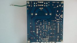
Pics of my board after smoking and a PDF of the schematic, which is very similar to Linuxguru's. I should add that I'll be changing my 2.2uf input cap to something else after very close scrutiny of Andrew T's observations on this component value in the scheme of things and I'll be backpedalling thru Clave's BOM with a fine toothcomb. A lot of my parts are crap stock Maplin's parts (it's only 300 yards away from my house lol) and I'll be paying close attention to non-magnetic, non-inductive upgrades.
Attachments
Last edited:
Now the tricky part. I later decided to add CL-60 to the board and run a safe earth wire from it's solder pad to the chassis earth post and attached the traffo centre tap directly to the PGND pcb lug as more usually done. AC1/2 connected as usual.
I powered up with amp still connected to the speaker (an oversight on my part). Immediately I started getting an intermittent loud crackling from the speaker, like someone scrunching up an empty crisp packet. Initially I thought there was a loose connection somewhere and started to investigate visually. Then after a couple of seconds SMOKE! From C1, (and possibly C2). I hit the mains power switch pretty damned pronto, let everything cool and discharge before disconnecting everything. Visual inpection reveals nothing I can see. No sign of burning on the pcb or C1/2 or anywhere for that matter.
I then connected my second board this time with no safety ground at all (yes I know) again no problem. So I'm mystified why the CL-60 to safety earth to PE method failed. Does anyone have any ideas what the problem is? Is it simply too much heat becuae of the CL-60, have I missed something or done something completely and utterly wrong?
...
Addendum: I'm using a 0-22 0-20 80v/a toroidal fraffo - just for initial testing!
I'm not sure if I understand the transformer windings - where does the centre tap come from? Is it there on both secondary windings? If not, then you have to derive it by connecting two of the terminals together - either 0 of one and 20 of the other, or 22 of one and 0 of the other.
With such a secondary combination:
1) The voltages on the two secondary windings have to be close - I'm not sure if 0-22 and 0-20 are close enough.
2) The phasing (polarity) of the two windings is important, as stated above:
0: AC1
22: PGND
0: PGND1
20: AC2
is one possible (correctly phased) connection. The same connection should be used on both boards.
3) If you accidentally interchange PGND with one of AC1 or AC2, smoke is a strong possibility - been there, done that.
Pics of my board after smoking
It seems that you're using an LM3886T (with a metal tab). The metal tab is internally connected to V-, so it is imperative that the tab be isolated from the chassis earth, all grounds, etc. The easiest way to do this is to use a mica insulator or similar when mounting it to the heat sink.
If the metal tab is not correctly isolated from ground, smoke and a destroyed LM3886T are likely outcomes. If you have to replace the LM3886, use the LM3886TF (isolated tab version) instead.
Last edited:
Thanks. Yes it's a T type. It is isolated with a dry silpad, i.e. no paste to avoid accidentally bridging the tab to sink. And I have a pair of the same connected the same way to the sinks in plain old fashioned LM3886 boards no problems with isolation whatsoever. I deliberately went with the T for reputed better heat dissipation. Still doesn't explain why one wiring method worked fine for an hour or so and not for 3 secs the other way. After dissassembly I did an olefactory diagnosis! C1 definitely smelled burnt, although there's no visual damage. Nothin else smelled. I don't think C2 was burning and didn't and doesn't smell. The smoke appeared to be coming only from C1 on the board edge side. Doesn't smell burnt at all today. Anyway I'll replace C1 and 2 to be sure and cautiously try again with CT to PGND faston and PE to the solder hole behind it. I'll remove CL-60 altogether for now as there's a suspicion of a dry solder on one leg. If it's good and the LM318 and the LM3886 seem to be working I'll do the appropriate electrical tests before re-attaching my speaker.
Perhaps the intermittent nature of the crackling was thermal shutdown on the chip kickin in and out if I hadn't tightened it up enough to the sink? But that still doesn't explain to my satisfaction why one wiring method (2 methods in fact) worked fine but the earthing via cl-60 didn't. Hmm. It may have to remain a mystery if I get it working again okay without the CL-60 and after replacing the caps.
Perhaps the intermittent nature of the crackling was thermal shutdown on the chip kickin in and out if I hadn't tightened it up enough to the sink? But that still doesn't explain to my satisfaction why one wiring method (2 methods in fact) worked fine but the earthing via cl-60 didn't. Hmm. It may have to remain a mystery if I get it working again okay without the CL-60 and after replacing the caps.
Last edited:
Pics of my board after smoking and a PDF of the schematic, which is very similar to Linuxguru's.
From the picture, it looks to me like one leg of C9 isn't soldered (I might be wrong of course). If that's the case, that could lead to the crackling - can't see why it would give smoke though.
Geoff
C1 definitely smelled burnt, although there's no visual damage. Nothin else smelled. I don't think C2 was burning and didn't and doesn't smell. The smoke appeared to be coming only from C1 on the board edge side. Doesn't smell burnt at all today. Anyway I'll replace C1 and 2 to be sure and cautiously try again with CT to PGND faston and PE to the solder hole behind it.
The polarity of C1 was correct, right? A vague possibility - the can of the electrolytic C1 was not isolated, and somehow came into contact with one of rails, and/or with the can of C2. It should not have happened with Panasonics (?) or similar.
From the picture, it looks to me like one leg of C9 isn't soldered (I might be wrong of course). If that's the case, that could lead to the crackling - can't see why it would give smoke though.
Geoff
It is soldered. Think you're looking at a solder hole next to the solder joint of one of the C9 legs. This is simply built in to allow different pitch size of C9 and is on the same track as the soldered leg. Thanks for takin the time to look over my soldering tho.
The polarity of C1 was correct, right? A vague possibility - the can of the electrolytic C1 was not isolated, and somehow came into contact with one of rails, and/or with the can of C2. It should not have happened with Panasonics (?) or similar.
Yes the polarity is correct if you see the pdf of my component layout in previous post. They're Nichicon Muses btw. Have to wait to make up a decent size componet order coz every company over here in UK seems to charge £4 for p&p so not worth just ordering 2 caps.
I'll see more of any damage and poss isolation problem when I hoik them out. The pcbs are just about transparent enough to see thru in strong light.
Thanks to all who have taken time out to look and/or comment. Any additional comments are very welcome.
I'm not sure if I understand the transformer windings - where does the centre tap come from? Is it there on both secondary windings? If not, then you have to derive it by connecting two of the terminals together - either 0 of one and 20 of the other, or 22 of one and 0 of the other.
With such a secondary combination:
1) The voltages on the two secondary windings have to be close - I'm not sure if 0-22 and 0-20 are close enough.
2) The phasing (polarity) of the two windings is important, as stated above:
0: AC1
22: PGND
0: PGND1
20: AC2
is one possible (correctly phased) connection. The same connection should be used on both boards.
3) If you accidentally interchange PGND with one of AC1 or AC2, smoke is a strong possibility - been there, done that.
Sorry Linux I missed this post🙄. Apologies I had a type in there. Its 0-22 and 0-22 and yes it's inphase. I only have one PGND faston on my board where your PGND is on your board but no additional PGND1 unlike yours so the middle 22 and 0 lines of the traffo are joined and connected to my single PGND.
I was also thinking that I may have interchanged PGND with AC1 or 2 in error and in haste. Unfortunately I didn't think to check that first before I disconnected everything so we'll never know😕
- Home
- Amplifiers
- Chip Amps
- The new "My Ref" Rev C thread