having heard the smear effect larger fkp2 caps exhibit, i decided to replace all the smaller valued bypass caps (>1nf) with soshin silver micas.
i could buy extras if anyone's interested in a pair. i've sourced all the required values through taobao (chinese ebay), which are 1nf, 220pf, 22pf, 10pf.
soshin also makes .1uf caps that look wickedly nice. just look at these copper leads! [³åË«¹Ú]ÈÕ±¾Ë«ÐÅSOSHIN ¶¥¼¶½ð½ÅQSϵÁÐ 0.1uF/100n/104Ħ»ú¼«Æ·-ÌÔ±¦Íø
Last edited:
2 X SOSHIN QS11 0.1uF 50VDC +/-1% PRECISION CAPACITOR! | eBay
same ones as these. much cheaper sourcing them from asian vendors, though.
ooh.. those were gold plated leads 😉
same ones as these. much cheaper sourcing them from asian vendors, though.
ooh.. those were gold plated leads 😉
MyRef RevO
Hello,
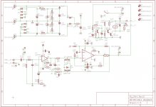
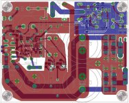
I've completely redesigned the PCB with the following goals:
Please, please help me to check both the schematic (especially the PS) and the PCB.
Any suggestion is welcome and greatly appreciated.
Hello,
I've completely redesigned the PCB with the following goals:
- large SMD usage, like in the Evolution
- New LM318 PS based on TL431, 14V with zener limiter (fig. 5b)
- Double diode bridge
- Larger caps
Please, please help me to check both the schematic (especially the PS) and the PCB.
Any suggestion is welcome and greatly appreciated.
Attachments
.
..- New LM318 PS based on TL431, 14V with zener limiter (fig. 5b)
- Double diode bridge
..
Dario, thanks for the schematic and layout.
I don't understand the main double-diode bridge rectifier circuit, but I'll try to digest it slowly.
I understand the zener limiter, but is it necessary?
Dario, thanks for the schematic and layout.
You're welcome Siva 😉
I don't understand the main double-diode bridge rectifier circuit, but I'll try to digest it slowly.
It's widely used for gainclones and power amplifiers, you can read something about it here.
I understand the zener limiter, but is it necessary?
It seems so, in the original MyRef's thread people started experimenting with higher voltages for LM318 (using 15V zeners or regulators) and Mauro Penasa warned that if the voltage swing from LM318 to LM3886 is bigger than a certain voltage it would trigger SPiKe protection and 12V was selected as a safe choice.
So, though it gave a not small sound improvement, people abandoned the higher voltage path...
We know from Evolution available data that it use a 28V limiter and LM318 works with +-14V.
In the 'RevO' I'm trying to implement the same thing.
While it's true that the Evolution uses a different and possibly more conservative compensation scheme but I don't think it is directly related with LM318 PS.
How abt an led string to regulate and supply voltage to opamp? Cheap and ultra quiet. Also it limits voltage, not just regulates. Quieter than zeners.
How abt an led string to regulate and supply voltage to opamp? Cheap and ultra quiet. Also it limits voltage, not just regulates. Quieter than zeners.
Hi Uriah,
the main problem using led strings in both applications is lack of space...
apart that the TL431 it's not a simple zener but a regulated voltage reference.
Probably not much better than zeners but...
In the voltage limiter the zener is completely isolated from the signal by the other diodes so there's not much to improve...
The zener+diodes pair limiter has also the great advantage of being very very compact.
From some photos I've seen the from the public documents published by Mauro about the Evolution his limiter should be pretty similar.
Sorry to interrupt the GURU conversation but we Neanderthals are still around.
...for my bi-amp project the active crossover I have on hand has balanced inputs. Which of these configurations, if any, will work best with the My-Ref?
I am aware of commercial adapters and DIY circuit designs but would like to avoid them for the sake of simplicity if possible. Will this approach introduce hum in the system or degrade the MyRef signal?
Last edited:
The xover inputs don't matter. OUTPUT goes to MyRef. Is that balanced? I doubt it, as most filters provide single-ended output.
This is not really a suitable topic for this thread. Neither is much more discussion about a totally revamped PCB design. I am very interested in it, but maybe it deserves its own thread.
Peace,
Tom E
This is not really a suitable topic for this thread. Neither is much more discussion about a totally revamped PCB design. I am very interested in it, but maybe it deserves its own thread.
Peace,
Tom E
Hey Tom,
Omission on my part. Both Xover inputs and outputs are the same. I'll be glad to take my questions to a different thread but I was also concerned with how this scheme might effect the quality of the MyRef sound, if at all.
As I have suggested previously, most people will follow the rules if they know what the rules are. It might be a good time to restate those topics that should be included and which areas go beyond that scope, I think it would be beneficial if you and maybe Siva, Dario, Uriah and whoever get together (through PMs or eMail) and create an outline. There is no problem for me - and I'm sure most members - to post elsewhere. I post to about six threads. Give us the definition that's appropriate and the off-topic posts can go where they belong.
Last edited:
This is not really a suitable topic for this thread. Neither is much more discussion about a totally revamped PCB design. I am very interested in it, but maybe it deserves its own thread.
Hi Tom,
I do agree, so I've started a new thread:
http://www.diyaudio.com/forums/chip-amps/196237-my_ref-revo.html
I'll wait your comments...
Dario
can i be the first one to say that i'm using mundorf supremes for 100nf spots? 😀
sounds beeeautiful!
silver/gold in c7 and supreme in c4 and c21. it actually feels like a tad bit less transparent than k72n's but remedies with smoothness and musicality.
i also swapped out rest of the bypass caps with oversized soshin silver micas and some antique copper film. didn't bother to a/b against fkp2s but i dont feel like there's any regression. music snaps and flows with perfect transients and there's more richness than a sandstate amp has a right to be.
still not as airy as fkp2 in c21 but when bg gets here, who knows? mundorf slver/gold might be the bypass cap of it's destiny.
i still detect that hardness in certain instruments but it's not even a distraction anymore. I could live with this! 😀
Last edited:
Click, Click
Boy do I not want to write this post. I seriously thought about a bold face lie but couldn't figure out how to make it sound believable. I rebuilt my "problem child" V1.2 red board three times in the last six months. In a final desperate attempt I decided to again, swap piece for piece between the good and the bad builds. My second item proved to be the knot in the garden hose blocking the flow. It was a Dale resistor clearly marked 470 at R-14. I had just overlooked that little "M" next to the number. A quick trip to my local Radio Shack and - Click - Click. All they had was 1/2 watt but I'm not complaining😀 The world is back in its proper orbit and the the birds are singing again.
So thru my total embarrassment what lessons can I pass along:
1. Don't trust the catalog numbers when starting your own sourcing. Always check with a meter where possible.
2. Build and use a dim bulb tester. Mine went to full off so I knew the circuit was complete even though it couldn't point to my specific problem.
3. Slow down and check as many parts as possible before mounting
4. Buy a cheap boom box from Best Buy and avoid all this stuff completely.
So I hereby take back half the nasty things I've been thinking and saying about all you DIYers.
Thanks ALL
Bob M. (AKA - The Michigan Moron)
Thanks Dario. Onward and Upward!!
I might just sit here for the rest of the evening turning the amp on and off.🙄
I might just sit here for the rest of the evening turning the amp on and off.🙄
Last edited:
Aha! Now I understand your email! Glad its singing Bob! Man, you have a lot of patience and persistence. Good for you and good job fixing it.
- Home
- Amplifiers
- Chip Amps
- The new "My Ref" Rev C thread