I have a prototype board that is acting up. I have had to ground it to the chassis as well as to the 0V on the dual secondaries. However, my kit amp like the ones you guys all have needs no special treatment. Also, my large caps have been in and out of many projects and have been soldered so much for so long that I have honestly worried about their long life, but so far so good. I think it may be hard to burn a cap that size. Could be done but I have had an iron on them for up to 30 seconds to get them out of other boards with big heat soaking copper planes as well as from large wires. Not saying thats not your problem but just saying that its not the most likely reason.
Sorry I cant help and can only comment right now.
Uriah
Sorry I cant help and can only comment right now.
Uriah
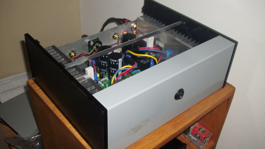
Woot, I got mine all finished up and its making my Wharfedales sing quite nicely 😀
I'll post a topless pic of the amp later, I'm busy enjoying the music right now!
I'll post a topless pic of the amp later, I'm busy enjoying the music right now!
A couple of pics
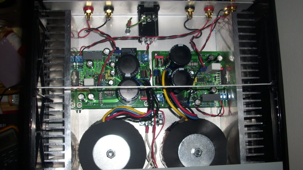
The heatsinks are way beyond overkill hehe, My speakers are 6 ohm and the sinks haven't even gotten warm to the touch playing for a couple of hours. I got the sinks from Barredboss on Ebay, I bought 1' of the 8.5" wide profile and had him cut it into 4 3" sections.
The heatsinks are way beyond overkill hehe, My speakers are 6 ohm and the sinks haven't even gotten warm to the touch playing for a couple of hours. I got the sinks from Barredboss on Ebay, I bought 1' of the 8.5" wide profile and had him cut it into 4 3" sections.
That's really a nice looking amp with an interesting layout. Do you get any hum with the chips "exposed" to the xformers?
What part of your amp came in that RCA box?
Peace,
Tom E
What part of your amp came in that RCA box?
Peace,
Tom E
Help Needed
Hi Troy,
Sorry, but it is still not clear to me which caps. Can you give me the C numbers Please.
Thanks
Pwr it up and see if the DC voltages are present on the primary filter caps.
Hi Troy,
Sorry, but it is still not clear to me which caps. Can you give me the C numbers Please.
Thanks
Andrew, Trust me the heat going into these sinks is so small that there is no need for ventilation. As he states they dont even get warm and I am sure that is 100 percent accurate. I use small cpu heatsinks which also get only bathwater warm. I would have no problem using one of his sinks for 4 MyRefC's. My bet is they would, at that point, get bathwater warm as well.
Uriah
Tony, I think he means the big caps.
Uriah
Tony, I think he means the big caps.
I do have a minor hum, inaudible unless I hold my ear a few inches from my speakers. But I don't blame that so much on the chips being close to the transformers. Its running off the same wall socket as my PC and some other noisy stuff, and my lm3875 amp I built has the chips even closer to the transformer with no hum at all running from a different outlet. I thought about getting an IEC socket with EMI filtration, but I already had the one I used from a local surplus store and I didn't want to wait on a digikey order.
The case isn't ventilated right now, but I wanted to get the amp working and I may add some holes beneath the heatsinks if it seems like they ever get very hot. And I might be removing everything at some point to repaint the chassis in semi-gloss black since I'm not a big fan of the industrial gray.
The RCA box is holding a spare 19J6 tube for my Millet starving student headphone amp, hehe.
Re: Help Needed
Peter
C3 and C8 (the BIG babies). Also perhaps C6 and C11 for the LM318 supply.Tony X said:Sorry, but it is still not clear to me which caps. Can you give me the C numbers Please.
Peter
Attachments
Re: Re: Help Needed
Thank you for answering for me Peter. I am just sitting down this morning and seeing the email.
Tony X-
Yes the largest caps on the board. I don't have the schematic handy to give you numbers but I think Peter was right.
schro20 said:
C3 and C8 (the BIG babies). Also perhaps C6 and C11 for the LM318 supply.
Peter
Thank you for answering for me Peter. I am just sitting down this morning and seeing the email.
Tony X-
Yes the largest caps on the board. I don't have the schematic handy to give you numbers but I think Peter was right.
Help Needed Update
Hi All,
Well, I powered up and checked voltages of C3 and C8.
C8 Charged to 30-31V but C3 did not charge at all.
I soldered a 200V 200µF cap on the underside respecting polarity. Still no charge.
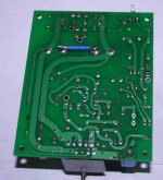
I desoldered the added cap and soldered a piece of copper wire between C3+ and C8- as these are both on the same trace on the other side of the board - see photo. On powering again I got a charge across C3 same as C8 and thought my problems were over. No luck, no sound came through. I did notice that the bulb took longer to dim (more capacitance to charge??).
I also noticed that on charging up the good board I can hear the relay clicking in. On the faulty board I don't hear it.
I rechecked all my soldering on the faulty board and found R16 not to be soldered on one leg. javascript:smilie(' ') However, soldering it correctly did not change anything.
I feel that I am going in the right diection but it's one thing after another.
I am learning a lot in the process but need a lot of hand-holding.
Any more suggestions?
Hi All,
Well, I powered up and checked voltages of C3 and C8.
C8 Charged to 30-31V but C3 did not charge at all.
I soldered a 200V 200µF cap on the underside respecting polarity. Still no charge.
I desoldered the added cap and soldered a piece of copper wire between C3+ and C8- as these are both on the same trace on the other side of the board - see photo. On powering again I got a charge across C3 same as C8 and thought my problems were over. No luck, no sound came through. I did notice that the bulb took longer to dim (more capacitance to charge??).
I also noticed that on charging up the good board I can hear the relay clicking in. On the faulty board I don't hear it.
I rechecked all my soldering on the faulty board and found R16 not to be soldered on one leg. javascript:smilie('
') However, soldering it correctly did not change anything.I feel that I am going in the right diection but it's one thing after another.
I am learning a lot in the process but need a lot of hand-holding.
Any more suggestions?
Attachments
Re: Help Needed Update
So at this point you DO have +/- 30 volts at the main filter caps (C3 + 8). And those caps are soldered on the board in the correct polarity putting +/- 30 on the correct rails of the PCB?
Tony X said:Hi All,
Well, I powered up and checked voltages of C3 and C8.
C8 Charged to 30-31V but C3 did not charge at all.
I soldered a 200V 200�F cap on the underside respecting polarity. Still no charge.
I desoldered the added cap and soldered a piece of copper wire between C3+ and C8- as these are both on the same trace on the other side of the board - see photo. On powering again I got a charge across C3 same as C8 and thought my problems were over. No luck, no sound came through. I did notice that the bulb took longer to dim (more capacitance to charge??).
I also noticed that on charging up the good board I can hear the relay clicking in. On the faulty board I don't hear it.
I rechecked all my soldering on the faulty board and found R16 not to be soldered on one leg. javascript:smilie('
I feel that I am going in the right diection but it's one thing after another.
I am learning a lot in the process but need a lot of hand-holding.
Any more suggestions?
So at this point you DO have +/- 30 volts at the main filter caps (C3 + 8). And those caps are soldered on the board in the correct polarity putting +/- 30 on the correct rails of the PCB?
So at this point you DO have +/- 30 volts at the main filter caps (C3 + 8). And those caps are soldered on the board in the correct polarity putting +/- 30 on the correct rails of the PCB?
Yes, Troy, but no sound coming out.
Ok I will print out the schematic and start looking for voltage test points.
I will also pull mine out and test those points for voltage.
Can you take a DETAILED picture of the top so I can see the diodes and their orientation?
I will also pull mine out and test those points for voltage.
Can you take a DETAILED picture of the top so I can see the diodes and their orientation?
Help Needed
That would be great, Troy. Thanks a million.
See attached.
Ok I will print out the schematic and start looking for voltage test points.
That would be great, Troy. Thanks a million.
Can you take a DETAILED picture of the top so I can see the diodes and their orientation?
See attached.
Attachments
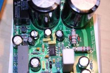
The rectifier only fits one way. Red diodes under the big 2W resistors look ok (a little hard to tell).udailey said:Troy may mean the rectifier diodes in front of the large caps.
Did you check polarity on all the electrolytic caps?
You said you don't hear the relay click. That suggests indeed that something is possibly busted with the power supply. Take look at the circuit diagram I posted a few posts up and see whether you can find the appropriate voltages near the supplies.
peter
Right. Sorry.udailey said:There are two diodes up front other than the rectifier D2 and D3.
Uriah
peter
- Home
- Amplifiers
- Chip Amps
- The new "My Ref" Rev C thread