ben_lesmana said:Troy,
Thanks for the tip. What's flux btw?
Ben
http://parts.digikey.com/1/parts/955607-flux-pen-formula-186-rma-83-1000-0186.html
Or you can buy solder that has a rosin core, which is flux.
It helps the solder flow better.
Uriah
It helps the solder flow better.
Uriah
I use "multi-core" solder and still use separate flux...
I am about to try the Silver content solders from PE but I can't decide if I want to get the low temp WBT brand (EXPENSIVE) or the higher temp Parts Express brand.
I will be doing some SMD parts soon and am concerned about the higher temp on the PE brand. (4xx* versus 3xx*)
I am about to try the Silver content solders from PE but I can't decide if I want to get the low temp WBT brand (EXPENSIVE) or the higher temp Parts Express brand.
I will be doing some SMD parts soon and am concerned about the higher temp on the PE brand. (4xx* versus 3xx*)
Help Needed
Troy,
Does the speaker have to be attached while doing these tests or is it safe under no load?
On the hot side of those caps you should have:
Troy,
Does the speaker have to be attached while doing these tests or is it safe under no load?
Speaker does not have to be connected. LM3886 are stable with no load.
I'd suggest that you turn the PCB on it's side on the heatsink and measure the solder joints from the "side"...
As long as you do NOT bridge 2 solder points you can put the DMM probe on every spot without damaging anything if the DMM is set for DC voltage.
You may even consider soldering a short piece of wire to the PGND tab and using alligator clips to clip on to that wire and the negative probe. That way you only have to hold one probe and watch one hand...
Be careful that in turning it on its side you dont let the weight of the board pull the legs of the LM3886 together into a short.
Uriah
Uriah
I've read enough horror stories now that I'd like to share a better experience to give those who haven't built their amps yet some confidence.
Stuffed both boards right away. I used Cardas lead-free tin/silver/copper solder and had no problems whatsoever. It costs $13 for a lifetime supply from Parts Connexion. Finally hooked one up today, using 22V 200VA traffo from Antek for each monoblock. I chose 22V tafos because I will be using these amps with low impedance speakers. Had problems hooking it up correctly, but I'll get to that. Finally got it right, attached to amp. Bulb tester flashed briefly, relay clicked. With shaking hands, attached cheapo speaker, powered up, bulb flashed briefly, crappy music played. Attached better workshop speakers, beautiful music played. Between tracks, cranked volume past normal listening level, no hum or any other noise with ear next to speaker. Seems totally silent. Heat sink getting slightly warm. I AM PUMPED!
I'll hook up the other board/traffo and test, then try it on my main system tomorrow: Marantz SA-11S1 SACD with Sonic Euphoria passive pre, B&W 802 speakers. That will be a real test of the quality, as I currently use (and am quite spoiled by) an ARC 100.2. If these little amps come even close, I'll be thrilled.
One sour note: compared to the amp I use in my workshop (power amp side of a big Nakamichi receiver thingy with outboard passive shunt resistance volume control), the My Ref seems ever so slightly bright. Not at all offensive, and perhaps just an artifact of not having run in the caps yet. Speaking of which, my coupling cap is a Vishay/Roederstein MKP1840 0.22uF. I plan to try some exotic stuff (maybe some Mundorf SIO or foil and film types) once I get enclosures made. I made no other changes to the stock kit, and it works perfectly.
About the transformers: there seems to be some confusion (at least, there was for me) about just how to hook these up. The primaries are paralleled. On the secondaries, test for continuity between leads. The two leads that do NOT have continuity are the ones to join and add the 0v wire at their junction. Of the other two leads, one goes to AC1 and the other to AC2.
Thanks to Uriah and Peter for their concept and dedication to its execution. I am very satisfied with the results. I strongly encourage you to build your kits. Take your time to get the parts situated correctly, which is really easy, and soldered neatly, which is not easy but can be done. Be cautious when initially hooking it all up. Once you know everything works, which it will, then let 'er rip!
Peace,
Tom E
madisonears said:I've read enough horror stories now that I'd like to share a better experience to give those who haven't built their amps yet some confidence.
.....
Thanks to Uriah and Peter for their concept and dedication to its execution. I am very satisfied with the results. I strongly encourage you to build your kits. Take your time to get the parts situated correctly, which is really easy, and soldered neatly, which is not easy but can be done. Be cautious when initially hooking it all up. Once you know everything works, which it will, then let 'er rip!
Peace,
Tom E
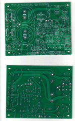
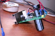
Built mine today, with my parts, up and working!
An externally hosted image should be here but it was not working when we last tested it.
Build your kits with confidence! With all the fantastic Peter's labels it should be easier than it was for me! 😉
Peter and Uriah, thanks again!
A successful GB!

I am thrilled and I know Peter is to. We are really happy that you all, Tony you will to, are enjoying your amps and that for the most part they are trouble free in building them.
Thanks for the thanks 🙂
Uriah
Thanks for the thanks 🙂
Uriah
Hi Clave,
post132 pic is super quality.
What are you using, hardware and software. What is your technique?
post132 pic is super quality.
What are you using, hardware and software. What is your technique?
Hi AndrewT,
nothing special, the digital camera is an old Pentax OptioS used in macro mode from a distance of ca. 30 cm.
Software side I've used Gimp only to recompress the jpeg for complying with ImageShack size policies.
nothing special, the digital camera is an old Pentax OptioS used in macro mode from a distance of ca. 30 cm.
Software side I've used Gimp only to recompress the jpeg for complying with ImageShack size policies.
Help Needed
Hi All,
Hi Troy,
I just finished testing and all was ok.
1. You should have ZERO resistance from the tie points of the following pairs of caps and PGND.
a. C3 + 8 ZERO
b. C6 + 11 ZERO
c. C1 + 2 ZERO
2. On the hot side of those caps you should have:
(for the C6 and C11 you can measure at the inside leads of R1 and R4 since they are raised and easy to get to.)
a. C3 = ~- 32.5 -31.3
b. C8 = ~+32.5 +31.3
c. C6 = +12 +11.7
d. C11 = -12 -11.7
e. C1 = ~-32.5 -31.2
f. C2 = ~+32.5 +31.1
g. C14 = +24 +23.7
Still no noise of relay clicking in.
I am going to go over all my solder points again.
Actually, even if it is frustrating that it is not working, I am really enjoying all this and learning a lot in the process.
Please keep your suggestions coming in.
Hi Tony,
something similar happened to me with one my second gainclone. Just stopped working and -36V at output!
All voltages seemed right, resistors were fine. Replaced the chip and all was working again!
So the relay not clicking in make me think that is doing it's job not passing DC. 🙄
If I've understood the schematic output ground is initially disconnected from power ground by the relay.
I think you could measure the output bypassing the relay from these points:
The DC measured should be in the order of few millivolts (mine il less than 6 mV)
If someone with a more solid knowledge of electronics could confirm it would be nice 😀
something similar happened to me with one my second gainclone. Just stopped working and -36V at output!
All voltages seemed right, resistors were fine. Replaced the chip and all was working again!
So the relay not clicking in make me think that is doing it's job not passing DC. 🙄
If I've understood the schematic output ground is initially disconnected from power ground by the relay.
I think you could measure the output bypassing the relay from these points:
An externally hosted image should be here but it was not working when we last tested it.
The DC measured should be in the order of few millivolts (mine il less than 6 mV)
If someone with a more solid knowledge of electronics could confirm it would be nice 😀
Help No Longer Needed!
Hi All,
Bingo.
I went over all the solder points that went through from the underside to traces on the top-side of the board.
I took off my piece of wire soldered between C3 and C8 and took out C3 and soldered it from the other side of the board to make sure I had a good contack with the trace going to PGND.
Wired up and switched on. Then heard that magic click of the relay and all is fine.
Thanks everybody. I might have tried something stupid otherwise.
Now I have to find a good cabinet. As we are not too far from Italy, it may come from there, you never know.
Am now turning off the soldering iron and going for a walk along the dunes. I think I deserve that.
Bye and good luck to all those who have yet to start.
Attachments
- Home
- Amplifiers
- Chip Amps
- The new "My Ref" Rev C thread