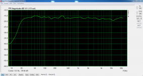
So, is it the frequency response of the driver in a closed box with a low pass filter around 70-80 Hz ?
then please show us the response with the MFB loop in the exact same conditions as previous graph.
I've never been myself able to get stables conditions at more then 9 - 10 dB of feedback (which is absolutely enough and sufficient to reach the maximum of the linear voice coil travel) so I'm extremely interested by your results
No, it is a measurement taken from the sensor in open loop.
Read this and all will become clear:
https://www.rmsacoustics.nl/papers/whitepaperMFBdesign.pdf
Robert is my partner in crime on this project.
Read this and all will become clear:
https://www.rmsacoustics.nl/papers/whitepaperMFBdesign.pdf
Robert is my partner in crime on this project.
So you think there is no design margin in 0.01% resistors? It may be the case, but I do not think that all resistors will have exactly that error. I did not measure them, so in the end it is speculation.
Not speculation, but statistics. No, not all resistors will have exactly that error. On the average, they will have half of that error.
The tolerance of the LSB is not so relevant
I think you are missing my point. I picked the LSB example because that is the easiest case to analyze understand, but it applies to all values / bit combinations. Linearity error is always the accuracy up to the last bit - so it is always up to the LSB.
If you disagree, please present an analysis. I already pointed out that we are talking about a voltage divider where the resistor values directly determine the current/voltage value.
Free field measurement complete speaker at 1 meter:

No smoothing.
Looks good! Wide and flat response. What kind of setup is it (drivers, form factor)? Are many IIR filters used? Is off Axis also reasonably flat?
Fedde
![_DSC2626[1].JPG](/community/data/attachments/709/709146-77c36dae10d4d5dc49890ac0d78c177b.jpg?hash=d8NtrhDU1d)
![_DSC2666[1].jpg](/community/data/attachments/709/709156-7d1530a30382ef6e7da7ddc9c49510c7.jpg?hash=fRUwowOC72)
Free field measurement complete speaker at 1 meter:
No smoothing.
No gating I meant.
I see... 🙄Size reference....
And the sub below will also be used in this setup? The 10" already goes low. Though larger units will help for high SPL...
Fedde
ds23man - congratulations!
My AINO speaker has SEAS L26ROY sealed downfire 8cm from floor, and despite 25Hz distortion hitting 100% around 105dB, it sounds really nice and potent enough! Did you try the Grimm woofer box upside down?
My AINO speaker has SEAS L26ROY sealed downfire 8cm from floor, and despite 25Hz distortion hitting 100% around 105dB, it sounds really nice and potent enough! Did you try the Grimm woofer box upside down?
Last edited:
The Grimm sub is the design of Rob and i did not have anything to do with it.
Rob and I teamed up to design a digital MFB solution for the Fusion amp.
Rob and I teamed up to design a digital MFB solution for the Fusion amp.
Is that solution available to mere mortals who don't drive Ferraris?The Grimm sub is the design of Rob and i did not have anything to do with it.
Rob and I teamed up to design a digital MFB solution for the Fusion amp.
I use Mr. Erath's feedback(servo) system but I would like to try yours as his is 60's technology. It still sounds good(actually very good as a lot of the old gear does) but I did hear the Grimm system at the Munich audio show and was impressed.
Is that solution available to mere mortals who don't drive Ferraris?
Yes, it will be.
Can a single 2 way fusion plats amp (fa252 or fa502) be used as a stereo amp? It was possible with the older plats amps from hypex (sa2.100)
I’m only dependent on the digital inputs.
I’m only dependent on the digital inputs.
Last edited:
No, it’s not possible.Can a single 2 way fusion plats amp (fa252 or fa502) be used as a stereo amp? It was possible with the older plats amps from hypex (sa2.100)
I’m only dependent on the digital inputs.
You have to select either left, right or legt+right(mono) channel.
Johan-Kr
No, it’s not possible.
You have to select either left, right or legt+right(mono) channel.
Johan-Kr
Thank you for clearing that out.
They can be bridged though, if you did want to set them up more as mono-blocks, still need two, put can spec a lower output and lower price variant, if that helps at all...
Yes, it will be.
Super cool. Any estimate on timeline? By end of the year?
- Home
- Amplifiers
- Class D
- The New Hypex Fusion Plate amps