So how much was the temperature differential between the 2 sinks due to the drivers and how different was the Vbe between the front and rear sink outputs ?
At the initial startup , all OP's were at 15mV (65ma) , after heating... front went up to a full 100ma, back to 50ma (2 to 1 almost). I am not biasing the drivers hard (150Re) , but they are quite likely the contributing factor. Nikko had the drivers on (smallish C shaped - tiny) separate heatsinks. Just the Vbe on the front heatsink only.
Luckily , I am real good at PCB work... 2-3 hours to correct this little issue.
(new board below) It is worth it , I love the sound of this amp.
OS
Attachments
Sorry
Hi OS, I am sorry. I don't know anywhere near enough to recognize any problem with your design. I look to you as the expert. I had no intent to let you walk into the wall.
Mark
No one advised me about my oblivious oversight. So many experts , no opinions.
In the end , by the "school of hard knocks" , I will blow by them like a jet airplane. So , again ... thanks for all the good advise (or the default silence , leaving me to my own devices). 🙄
OS
Hi OS, I am sorry. I don't know anywhere near enough to recognize any problem with your design. I look to you as the expert. I had no intent to let you walk into the wall.
Mark
Just Venting. 😀 Anything that does not absolutely discourage one will only make them stronger. I am etching now. 🙂
Maybe I can start a discussion Drivers on separate heatsinks Vs. the OP stage as one thermal "block" ???
OS
Maybe I can start a discussion Drivers on separate heatsinks Vs. the OP stage as one thermal "block" ???
OS
At the initial startup , all OP's were at 15mV (65ma) , after heating... front went up to a full 100ma, back to 50ma (2 to 1 almost). I am not biasing the drivers hard (150Re) , but they are quite likely the contributing factor.
I heard one amplifier which has same bias increasing. If you push it hardly, and the heatsink temperature rising the bias goes up, more than twice, as with cold heatsink. But it goes down if no signal applied.
And this amplifier sounds very good!
Sajti
if you are expecting to use brass heat sink you should read the table in the link below copper is very different and have a much lower thermal resistance
Thermal Conductivity of Metals
Thermal Conductivity of Metals
Now at moderate volume ... everything is better. Best Mongrel of all. 🙂 WOW.. really!! No particular area(part/portion) .. actually all of them.
ONE FATAL FLAW 😱 🙁🙁 having the drivers on just one of the heatsinks makes the front heatsink bias harder than the back one (the one without the drivers). I will etch 2 more boards with the drivers on a brass plate in front of the outputs.
Amp will thermally stabilize , but with the front OP's biased twice the rears 😱 . Drivers are adding to the Vbe.
The boards are almost redesigned (below 1) same circuit (IT'S PERFECT) ,just an anal "thermal issue". Another chapter in R/D. 😱
Even as a "fucup", this is a awesome sounding amp. 😀
OS
Thanks a lot for that , audiofan ! Brass sucks (64)... Aluminum (124-144) it is. Wish I could find some copper plate (224).
OS
OS
Thanks a lot for that , audiofan ! Brass sucks (64)... Aluminum (124-144) it is. Wish I could find some copper plate (224).
OS
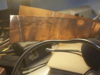
Duz da Mrs. have any of those copper clad cooking pans around????


I have some, this about .015 thick and as you can see Very ExpensiveThanks a lot for that , audiofan ! Brass sucks (64)... Aluminum (124-144) it is. Wish I could find some copper plate (224).
OS
Attachments
Time to rig up a propane furnace and make a mold...
- keantoken
I think OS is disappointed because they have a lot of copper left over from the old stills up in da woods..... 😀😀😀
I can give you some of these ... 😛
Best regards - Rudi_Ratlos
An externally hosted image should be here but it was not working when we last tested it.
Best regards - Rudi_Ratlos
I think OS is disappointed because they have a lot of copper left over from the old stills up in da woods..... 😀😀😀
That is why the copper is so rare , we used it all up. 😀 Stainless steel is what the modern still uses.
I have researched the thermal requirements of the drivers and found that at 220Re (6.5ma idle) the heatsink can be quite small . look at the Leach amp (220Re) with its real small 16C/w HS's. the nikko was no different with
6-8 sq. cm "U" shaped OEM cheeepo's. 🙁 ASKA 100's use 40 X 40 mm copper squares and a lot of HT OEM's use NOTHING. My 150Re idles at 10mA and will have to pass 200ma on transient loads. My guess is that 4-5 C/W for both (a 25 X 100mm aluminum strip) will be more than adequate.
I did use 2- 12C/w's for the drivers on my "supersym" , they became slightly hot (40C+) with 4 pair OP and heavy load.
OS
Last edited:
Time to rig up a propane furnace and make a mold...
I've been thinking exactly that; I've been saving pop cans from around the neighborhood for 4 months in anticipation. 🙂
It would be nice just to have a good furnace and machining stuff so you can pretty much make anything at home. Christmas gifts? Make a heavy toaster. Or a solid steel dough roller. Precision garlic press. A silent aquarium air pump (joys). Sharpened indestructible soup ladle, for unparalleled scooping power (for cooking and self-defense)!
- keantoken
- keantoken
I've been thinking exactly that; I've been saving pop cans from around the neighborhood for 4 months in anticipation. 🙂
My Fet preamps are using the heat sink materials that you describe. 🙂
It would be nice just to have a good furnace and machining stuff so you can pretty much make anything at home. Christmas gifts? Make a heavy toaster. Or a solid steel dough roller. Precision garlic press. A silent aquarium air pump (joys). Sharpened indestructible soup ladle, for unparalleled scooping power (for cooking and self-defense)!
- keantoken
I melt aluminum on a oak fire in a coffee can. 😀 Really ! Used DIY solder also gets cast into fishing sinkers/lures and for tinning new PCB's
Back to the "grind" (amps)... the final EX/AX modules are tested and done (I am listening to both).
We need a good power board to go with them (below 1) is mine and (below 2) is everyone elses (NEW pb120). Same cap MUX's , more room for bigger caps , "compact MUX" (1 sq. inch per mux) I almost have" below 2" done. Size wise , I really don't think 4" X6" (100 X 150mm) is too big. Too many boards at DIYA have too many OP devices.. too close together 🙁. In the real world this is not ideal. I am going to pack this board with 4 -32mm power supply caps so all one would need is a bridge and trafo 🙂 .
I also will do a PB300 SUBWOOFER board (still 100 X 150mm) , no cap MUX ... but Locanthi triple with mje340/350 - njw0281/0302 (the drivers) - njw21193/94 X 3 pair OP(PB150sub). This will be the next new board I etch.
PS - modules will attach at 90 degree angle and be not much higher than the big supply caps. In total, much less space than standard separate PS/amp (100 X 150 X 100mm square)
OS
Attachments
On board #2, I see power for all six output devices that are used for one channel; but, where are the other three output devices?
On board #2, I see power for all six output devices that are used for one channel; but, where are the other three output devices?
Board 2 only has 4 OP's , same as my nikko. the 6 OP sub amp is not shown (I have not done it yet. The power on board 2 can be either single supply (55-0-55) or dual supply (55-0-55V and 65-0-65V). The jumpers on the cap MUX's let you tie into the OP rails. Universal for those with just 1 supply. (Below 1 and 2)
are the new PB120 & 150. The 150 will be triple and just might be a 200 8R/400 4R amp. The 120 will have 2 -30mm 10,000uf caps and the 150 will have 4- 32mm 10kuf caps .
OS
Attachments
Oh, I feel blind!!! The 120 is flat mount with 4 op?
Okay, but flat mount will need some air holes. 🙂
What's the recommendable voltage for the 120 with a 4 ohm load? I've actually no intentions for a 4 ohm speaker on this amp, but I'd like to know an "everything works" voltage figure. 🙂
Okay, but flat mount will need some air holes. 🙂
What's the recommendable voltage for the 120 with a 4 ohm load? I've actually no intentions for a 4 ohm speaker on this amp, but I'd like to know an "everything works" voltage figure. 🙂
Oh, I feel blind!!! The 120 is flat mount with 4 op?
Okay, but flat mount will need some air holes. 🙂
What's the recommendable voltage for the 120 with a 4 ohm load? I've actually no intentions for a 4 ohm speaker on this amp, but I'd like to know an "everything works" voltage figure. 🙂
120W "flat mount" does not need "air holes". 😕 OP device die heat-spreaders lie flat on mica/heatsink. All you need do is drill 5 holes ( 1 for Vbe and 4 for the OP's) screw in with self tapping screws. 50-0-50V with 2 - 10 or 12.6kuF @63V caps will work fine for 4R and 8R. For just 8R, 60V+ with 2-30mm 80V - 8200uf caps (better transients/peaks).
The 150 will be a "work of art". 4 big caps right at the OP's (mjl21193/4) , triple op ... the ultimate "blameless". 🙂
OS
- Home
- Amplifiers
- Solid State
- The MONGREL (supersym II)