As I said that level of transient ringing with complex loads is completely irrelevant and unavoidable, it is safe if it meets Lyapunov criteria and this case is exponentially stable.
Lyapunov stability - Wikipedia, the free encyclopedia
Lyapunov stability - Wikipedia, the free encyclopedia
OP coil / relay board done , LT CD4000 series trouble.
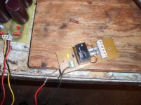
I finished the physical job (below 1). Ran the relay at 22 V (hey , its a 24V relay) ... any ideas on how to run a 24V device with a 12V logic circuit ?? (below 2).
The logic circuit - 2 -4001 nor gates act as a astable gated oscillator which also flashes a LED. The oscillator output is the clock input for the 4017 decade counter which toggles from O0 to O9. Diode OR gates turn on "SS" at 6 seconds and "PR" at 10 seconds. When "PR" goes high , the clock is disabled. Any pulse (turnon or turnoff) or a high output from a analog DC/over-current protection chip will reset the counter either temporarily or permanently , engaging the clock/LED but keeping the counter at "O0" (relay will stay open).
Built this thing in 1984 .. had to remember how to do it. (no LT spice then).
OS
I finished the physical job (below 1). Ran the relay at 22 V (hey , its a 24V relay) ... any ideas on how to run a 24V device with a 12V logic circuit ?? (below 2).
The logic circuit - 2 -4001 nor gates act as a astable gated oscillator which also flashes a LED. The oscillator output is the clock input for the 4017 decade counter which toggles from O0 to O9. Diode OR gates turn on "SS" at 6 seconds and "PR" at 10 seconds. When "PR" goes high , the clock is disabled. Any pulse (turnon or turnoff) or a high output from a analog DC/over-current protection chip will reset the counter either temporarily or permanently , engaging the clock/LED but keeping the counter at "O0" (relay will stay open).
Built this thing in 1984 .. had to remember how to do it. (no LT spice then).
Yes , you all can "nitpick" while I build ... haah!Frankly, I think much of this is nitpicking
OS
Attachments
Last edited:
To get the three benefits you're supposed to get from Miller Compensation:
1) create dominant pole - to lower total loop gain below unity before oscillation frequency is reached
2) "pole splitting" - ie. the pole at the pre-driving stage's collector is pushed up in frequency as the pole at the driver stage's collector is pulled down.
3) "linearize" VAS - reduces VAS gain with "local" NFB
You need to size Cdom to sufficiently lower the unity gain frequency, minimize source impedance to the stage that's getting compensation and ensure that the source is capable of delivering the necessary current expected. This example (Q115 and Q119) doesn't have any impedances placed between them.
http://www.diyaudio.com/forums/soli...lls-power-amplifier-book-164.html#post2547074
Miller compensation is not always necessary and in the context of "KISS", not always desirable either. The various Symasym boards seem to do fine without it.
Probably I wrongly called it Miller capacitor as drivers are emitter followers. In my simulation adding those capacitors did not change anything.
Regarding the ringing I thing that simple improvement as decreasing base stopper for drivers is good, because having les ringing whit this simple change is better then to say that this ringing is not important. Sor some type of output BJTs(MJ21194/95) it was necessary to remove driver base stopper completaly.
dado
I get a smoother AC curve when sim with 4.7 Ohm than with original 68 Ohm.
So, what dadod say makes good sense.
Regarding distortion on the final AX it is vanishing low. Like 0.00012%-0.00025%
From 1 Watt and upto 120 Watt.
Thanks to TMC correction, I gather.(100p/430p/820ohm)
Regarding ringing on capacitive load one more thing.
Value of the resistor(R98) parallel to the L1, I think, is to hight. Best result I've got with 2.2 ohm. Try to play with different values.
dado
Value of the resistor(R98) parallel to the L1, I think, is to hight. Best result I've got with 2.2 ohm. Try to play with different values.
dado
Probably I wrongly called it Miller capacitor as drivers are emitter followers. In my simulation adding those capacitors did not change anything.
Regarding the ringing I thing that simple improvement as decreasing base stopper for drivers is good, because having les ringing whit this simple change is better then to say that this ringing is not important. Sor some type of output BJTs(MJ21194/95) it was necessary to remove driver base stopper completaly.
dado
Yes , I will change my driver basestoppers to 10R (have a million of them) , your advice was proven by LT.
Regarding ringing on capacitive load one more thing.
Value of the resistor(R98) parallel to the L1, I think, is to hight. Best result I've got with 2.2 ohm. Try to play with different values.
dado
They are just the 2 components for L//R LP filter - 2.5uh/10R = 1.25uH/4.7R = .6uH/2.2R .....
Regarding distortion on the final AX it is vanishing low. Like 0.00012%-0.00025%
That looks exactly like my 1Khz simulations - 1 -3 PPM. At 20K , 8-10ppm (.0008 -.001%). The way it slewed on the real squarewave test , I would expect 100-125V/us , at least 3 times better than Doug Selfs amp. I do use better parts (fairchild KSA/KSC) , so this would be expected.
OS
Hi OS, Just a little more "nitpicking" about both coils, put both windings in the same direction to minimize mutual coupling
Cheers
Arturo
Cheers
Arturo
Are we chasing Ghosts ?
" In actual fact, by far the most important factor affecting overshoot and ringing is the rise time of the applied square wave. This is yet another important audio fact that seems to be almost unknown. " D.Self
" In actual fact, by far the most important factor affecting overshoot and ringing is the rise time of the applied square wave. This is yet another important audio fact that seems to be almost unknown. " D.Self
Hi OS, Just a little more "nitpicking" about both coils, put both windings in the same direction to minimize mutual coupling
Cheers
Arturo
I meant no disrespect as far as my "nitpicking" comment. I did orient both coils the same direction (L mirrors R). I even put a ground between L/R and gave them extra distance. I adhered to the Nikko's layout with minor improvements.
So far ...
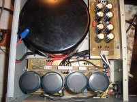
a. Increased main filter caps from 2 X 15kuF to 2 x 16.2kuF with a 35A heat-sinked bridge.
b. Got rid of the "cheezy" 2 X 1kuF 70v supply with no Hf decoupling and replaced with a true C-R-C 8 X 470uF unit.
c. Used the same grounding scheme as the Nikko , with it's dual returns to isolate OP switching pulses from the small signal paths.
d. The design itself is better (PSRR wise) , the nikko was a goldmund/symasym type balanced VAS with no local decoupling or current sources. 😱
e. Added the cap multipliers to further enhance the small signal sections PSRR.
All this - plus the fancy protection circuit, will grace this thread in time (I am not paid) after it has endured a little summer heat and my picky ears. Documentation and "anal" layouts that won't cost a fortune to build and last 20 years are around the corner .... No fine wine before it's time. 😀
OS
" In actual fact, by far the most important factor affecting overshoot and ringing is the rise time of the applied square wave. This is yet another important audio fact that seems to be almost unknown. " D.Self
I was using a "homebrew" 1 and 10Khz SW oscillator with over 300V/us using a fast op-amp. So the possibility of using too fast of a test signal could explain the overshoot. LT with 10e9 risetime exhibits more overshoot that 10e8 , for example. 😕
OS
" In actual fact, by far the most important factor affecting overshoot and ringing is the rise time of the applied square wave. This is yet another important audio fact that seems to be almost unknown. " D.Self
Yes, at very high dv/td impulses it is unavoidable in real amps. with real loads + internal parasitics, stored charges, device internal instability regions .... What is really important is a rapid recovering (convergence) to a stable condition (short transient), anyway there are topologies and component choosing that minimizes the amplitude and duration of this condition. Do not rely on simulator regarding transients, reality is usually worse.
Hi OS, neither me, someone else put that word in a comment, that put a smile on my face, I think this discussion is serious enough, but a little bit humour never hurts, that why I used that catchword as you did, isn't it?I meant no disrespect as far as my "nitpicking" comment.
....
OS
Cheers
Arturo
A real fine line between "nitpicking" and "serious enough". I did this test (while my CRO was operational) on the "real" original nikko and a JVC power amp. They did the same thing (overshoot). What I would like to know is what effect on the final sound will varying degrees of this errata have or whether extreme speed/slew factors are just "mental masturbation". 😀 It was a good learning experience which will influence my design choices ...10R base-stoppers (thanks ,Dadod).
Hopefully this amp will put a silicon image ULD or a standard "blameless" to shame.
OS
Hopefully this amp will put a silicon image ULD or a standard "blameless" to shame.
OS
" In actual fact, by far the most important factor affecting overshoot and ringing is the rise time of the applied square wave. This is yet another important audio fact that seems to be almost unknown. " D.Self
I was using a "homebrew" 1 and 10Khz SW oscillator with over 300V/us using a fast op-amp. So the possibility of using too fast of a test signal could explain the overshoot. LT with 10e9 risetime exhibits more overshoot that 10e8 , for example. 😕 OS
Ahhh yes - da old PMEL repair and calibration technician part of my past raises it's pointed little head and sez - "check your signal sources duuuuude"!! 😀
Your testing can only be as good as your signal source - and in the calibration lab we were required to use sources that were a power of 10 better than the device under test.
Also - remember that your test probes and cables are an important part of the measurement package. People can argue all they want about good speaker cables buuuuuut good cables from your signal sources (in this case an audio freq. generator) and your measurement device (o'scope) must be of a very high grade. Annnnnnd - don't forget to calibrate your scope probes!!!
Juz trying ta help - no bad vibes intended!! 😉
To date I have not seen any "stable" real amp free from this transient effects, and given that it is very unlikely that real "music" material ever have such high dv/dt, this subtleties will never happen. A barely stable amp will go unstable with much less stress. Stability is a hairy issue that goes far beyond nyquist, PM ... , simulators gives a good approach helping test all foreseeable conditions, but doesn't guarantees the final result. The rest you know is building and experimenting. For me it is good to have high slew and a low distortion of al least 100KHZ BW = transparency, so if you have something to blame, blame anything else. I am now in a radical design which surpass the "blameless" by orders ... 400V/usec, 1ppm 20KHZ, 56ppm 200KHZ ... and rock solid stability, I do this because I like it, even if isn't necessary, my philosophy is always go beyond ... he heA real fine line between "nitpicking" and "serious enough". I did this test (while my CRO was operational) on the "real" original nikko and a JVC power amp. They did the same thing (overshoot). What I would like to know is what effect on the final sound will varying degrees of this errata have or whether extreme speed/slew factors are just "mental masturbation". 😀 It was a good learning experience which will influence my design choices ...10R base-stoppers (thanks ,Dadod).
Hopefully this amp will put a silicon image ULD or a standard "blameless" to shame.
OS
Cheers
Arturo
more mental masturbation...
Consider that many sources contain "sluggish" op-amps (LF353 = 9-10V/uS) or NE5532. From performance to speaker , there are at least one of these devices in the chain. Of course , one could create the source. My VST synthesizer will create a sawtooth waveform with 50+ V/us rise time right out of the sound card.
Soooo , even if your sound card has SMD OPA devices (500v/us) , the slew would be only as fast as the weakest link (source/or devices). To go overboard with 200V/uS might increase the likelihood of a tweeter failure 😱 .
OS
Yes, the lowest slew within the chain (except in the simms). Practical feeding slew's will never reach that high, so it is more likely that clipping is the responsible of tweeter failures. But slew is also related to BW, stability and distortion at high freq. you may have 1ppm at 1KHZ but 10000ppm at 10KHZ (still audible freq,) if the slew is too low, so high slew's are part of the "blameless" equation (and of course good selling)....
Soooo , even if your sound card has SMD OPA devices (500v/us) , the slew would be only as fast as the weakest link (source/or devices). To go overboard with 200V/uS might increase the likelihood of a tweeter failure 😱 .
OS
Cheers
Arturo
Some clarification to avoid misunderstundings, the lowest slew is propagated throught the chain does not imply it will be the "that" slew at the end point, becuase we must consider amplifications and attenuations at the different nodes that travels the signal, so my prior comment is valid only with a unity gain chain.
Last edited:
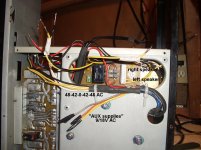
I'm still burning it up with square waves 😀. I won't do my first audition till I get some blue wire for the negative rails and the euroconnectors for the AX modules. It is almost the same as my last 250W version , but more refined. that one had tremendous headroom and a huge soundstage. This one (in the Nikko case) is the first one with true separate supplies , so the definition should be even better. With the steel case and shielded trafo , it will be quieter as well.
(below 1 and 2) , I have it almost wired ... including the relay board. I don't want to wire it twice ... so I need 18ga. blue wire. I plan on gold input jacks and other "frills". 😀
There will be 8 PCB's when I am finished ( 2 AX modules , 2 power boards , 2 power supply boards , the relay/coil board , and the protection circuit) ... actually 9 - the fancy power meter that came with the Nikko.
OS
Attachments
- Home
- Amplifiers
- Solid State
- The MONGREL (supersym II)