With the output of the amp DIRECT to the load (1uF/8R- below 1) I get " ringing" . With the output hooked to the L/C output network (below 2) (1.5uH/10R).. it goes away. 😕 I tested in the real world without the L/C , is it possible that this network negates the transient "errata"?? I sort of trust LT , but I have no scope now ... no other choice. Klewis , did your CRO test include the full output zobel/ inductor networks ???
OS
I went back and re-read your post, so, here is Part two: my understanding is that the amp will ring into a 1uf/8R load even with zobel and inductor installed. This is what PaulBysouth told me regarding ringing "You cannot stop the load after the inductor from ringing (would need infinite current). The 1uF load here needs 36 Amps to go from -20v to +20v in 1uS." I believe the point of the C||R test is to make sure that the amp doesn't go nuts or up in smoke when driving significant capacitance. But, it shouldn't ring in the absence of significant capacitance.
Ken
That makes me "feel better" 🙂 LT confirmed my theory about the OP inductor , that's why I asked you whether you did the test WITH one. there is not much that can go wrong with a "blameless" ... especially this one. It has universal compensation capability , REAL GOOD short runs in the layout , very few long parallel lines (low parasitics) ... even 2 separate power supplies. I think it will be VERY good (below).
The amp(s) both survived the 10R/4.7uF test at 60Vp-p SW overnight. 😱 good to go full duty (let the kids/wife blast it)
The fit in the nikko case is exceptional. 🙂🙂🙂 looks like it was made in japan - military duty class (way more HD than OEM's)
OS
The amp(s) both survived the 10R/4.7uF test at 60Vp-p SW overnight. 😱 good to go full duty (let the kids/wife blast it)
The fit in the nikko case is exceptional. 🙂🙂🙂 looks like it was made in japan - military duty class (way more HD than OEM's)
OS
Attachments
Last edited:
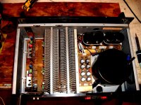


Thank you... C2C. Not a easy one ... much planning. A normal DIY amp with conrad heatsinks , antek trafo , and roomy interior would be a "walk in the park" to layout. I have the neighbors original Nikko 230 alpha to compare to this one as well , I do think this one will outperform the original in noise , power , and mean time between failure (30 years... aye) 😀.
I might buy some more broken ebay amps to retrofit ... this is fun . 🙂
OS
I might buy some more broken ebay amps to retrofit ... this is fun . 🙂
OS
Very nice job!
I see those types of heatsinks in current commercial equipment here in Japan a lot, and they are incredubly efficient.
I see those types of heatsinks in current commercial equipment here in Japan a lot, and they are incredubly efficient.
Thanks , Hugh 🙂Elegant job, Pete.... now build quantity and sell a few, OK?
Hugh
That is how I built this: sold 4 amps = paypal = ebay amp + mouser orders. Still , I have no "warchest" of funds ... so things are slow. 🙁 On the topic , I will offer a module/power board combo for the DIYA "boardstore". Other designs , like a nice triple for sub use , and a complete AX "kit" .. I will handle.
By Bonsai - Very nice job!
I see those types of heatsinks in current commercial equipment here in Japan a lot, and they are incredubly efficient.
I truly admire Japanese engineering .. (on par with German craftsmanship) , those heatsinks are amazing !!! Full night of that 60v p-p cooking those 95w resistors and the HS's were convecting admirably , turn off the SW and they cool down in 60 seconds !! A large version of the best Zalman CPU thermal solutions !
OS
OS,
Looking your schematic I noticed that you use 68ohm as predriver base resistor(R86, R87).
I had similar problem with to much ringing on 8ohm//1uF load.
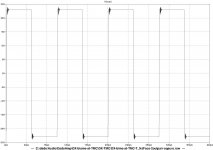
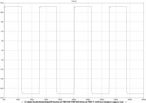
I used 33ohm on that possition and when I decresed them to 4.7ohm ringing was much smaller. Value of this resistors depends on type of output BJTs. Miller caps on predriver are not needed I think as my simulation(on my very similar amp) does not show any difference with or without them.
First simulation is with 68ohm and scond is with 4.7ohm all on 8ohm//1uF.
Looking your schematic I noticed that you use 68ohm as predriver base resistor(R86, R87).
I had similar problem with to much ringing on 8ohm//1uF load.
I used 33ohm on that possition and when I decresed them to 4.7ohm ringing was much smaller. Value of this resistors depends on type of output BJTs. Miller caps on predriver are not needed I think as my simulation(on my very similar amp) does not show any difference with or without them.
First simulation is with 68ohm and scond is with 4.7ohm all on 8ohm//1uF.
Attachments
Maybe you should better test your amp at 1/3-1/2 full power, that will lead to maximum dissipated power in BJT.
Running Amp at max power lead to max efficiency.
Running Amp at max power lead to max efficiency.
Run it at 1/3 to 1/2 maximum power for a short time only.
It will heat up rapidly.
Try 5seconds. If it's cool to cold then try 30seconds. If it's warm to cool, try 2minutes.
If it's hot, then stop there.
It will heat up rapidly.
Try 5seconds. If it's cool to cold then try 30seconds. If it's warm to cool, try 2minutes.
If it's hot, then stop there.
I made lot of simulation on my amplifier, because I found heavy ringing with 8ohm+0.1uF load.
My experience, that I can cancell the oscillation if I cut the HF range, with 100kHz -3dB, and decrease the nfb. I did lot of changes in the output stage, but only this solution was helpful.
After the lot of time spent with simulation I put the output coil (0.5uH), with parallel 1ohm resistor. And the amplifier is stable with ANY load, and about 40dB of feedback. The frequency range goes up to 500kHz.
So I think that this coil is better solution, than any other.
Sajti
...
After the lot of time spent with simulation I put the output coil (0.5uH), with parallel 1ohm resistor. And the amplifier is stable with ANY load, and about 40dB of feedback. The frequency range goes up to 500kHz.
So I think that this coil is better solution, than any other.
Sajti
yes, and the coil also prevents the "antenna effect" of the speaker cabling catching RF and injecting in the NFB network.
speaking of coils ....
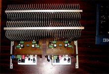
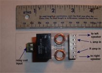
I am copying nikko's idea for the OP inductor. In fact , I am using the original components. Just curious , the Nikko coils (below 1) are 12 X 12mm (.5 X .5 ") with 12 turns ... this equals 1.25uH Air Core Inductor Coil Inductance Calculator .
They combined this with a 4.7R/ 3w resistor in series - this gives me (below 2) , @800Khz -3db cutoff (good for the job - RF suppression).
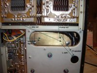
Placement wise (below 3) , I will out-do the nikko (they ran amp/coil /relay/switch in front/ speaker jacks in back) .. that is a LONG run for the output. My "scheme" is to just go amp/coil/relay/output jacks in as short a run as possible. I can switch my speakers on/off by just toggling the relay , eliminating the "loop" to the front switches.
Now for the magic 4017 cmos/ta7317 protection circuit. I will have a relay'ed output (tonight).
OS
I am copying nikko's idea for the OP inductor. In fact , I am using the original components. Just curious , the Nikko coils (below 1) are 12 X 12mm (.5 X .5 ") with 12 turns ... this equals 1.25uH Air Core Inductor Coil Inductance Calculator .
They combined this with a 4.7R/ 3w resistor in series - this gives me (below 2) , @800Khz -3db cutoff (good for the job - RF suppression).
Placement wise (below 3) , I will out-do the nikko (they ran amp/coil /relay/switch in front/ speaker jacks in back) .. that is a LONG run for the output. My "scheme" is to just go amp/coil/relay/output jacks in as short a run as possible. I can switch my speakers on/off by just toggling the relay , eliminating the "loop" to the front switches.
Now for the magic 4017 cmos/ta7317 protection circuit. I will have a relay'ed output (tonight).
OS
Attachments
OS,
Looking your schematic I noticed that you use 68ohm as predriver base resistor(R86, R87).
I had similar problem with to much ringing on 8ohm//1uF load.
I used 33ohm on that possition and when I decresed them to 4.7ohm ringing was much smaller. Value of this resistors depends on type of output BJTs. Miller caps on predriver are not needed I think as my simulation(on my very similar amp) does not show any difference with or without them.
First simulation is with 68ohm and scond is with 4.7ohm all on 8ohm//1uF.
To get the three benefits you're supposed to get from Miller Compensation:
1) create dominant pole - to lower total loop gain below unity before oscillation frequency is reached
2) "pole splitting" - ie. the pole at the pre-driving stage's collector is pushed up in frequency as the pole at the driver stage's collector is pulled down.
3) "linearize" VAS - reduces VAS gain with "local" NFB
You need to size Cdom to sufficiently lower the unity gain frequency, minimize source impedance to the stage that's getting compensation and ensure that the source is capable of delivering the necessary current expected. This example (Q115 and Q119) doesn't have any impedances placed between them.
http://www.diyaudio.com/forums/soli...lls-power-amplifier-book-164.html#post2547074
Miller compensation is not always necessary and in the context of "KISS", not always desirable either. The various Symasym boards seem to do fine without it.
Hello , as I see you are new here , so I'll be easy. 😀
#1, most "know of" miller compensation. This amp (the mongrel) can do miller , 2 -pole miller ,and transitional. How it is implemented and what values are determined by the transistors and the topology.
Some old slow devices with huge Cob (base capacitance) could get away with no miller comp. , the output devices were also so slow oscillation was minimal.
"mid speed" devices (mje340/50) need miller comp. they will oscillate unless given a dominant pole. 22 - 47 pf is the sweet spot for these devices either in a symasym type design or blameless/cordell example.
Newer Ksa1381/c3503's are speed demons , with only 3-6pf cob , they need a larger miller capacitance to set the pole to something reasonable. (47-82pF)
#2 , the symasym HAS a miller cap (C7 - below) , it also has 2 shunt capacitors (C3-4) plus the VAS is loaded to ground (r18/20). This arrangement has multiple poles and zero's. Without this network it would not "be fine" , frying your parts and speakers quickly. 😀
OS
Attachments
Hello , as I see you are new here , so I'll be easy. 😀
#1, most "know of" miller compensation. This amp (the mongrel) can do miller , 2 -pole miller ,and transitional. How it is implemented and what values are determined by the transistors and the topology.
Some old slow devices with huge Cob (base capacitance) could get away with no miller comp. , the output devices were also so slow oscillation was minimal.
"mid speed" devices (mje340/50) need miller comp. they will oscillate unless given a dominant pole. 22 - 47 pf is the sweet spot for these devices either in a symasym type design or blameless/cordell example.
Newer Ksa1381/c3503's are speed demons , with only 3-6pf cob , they need a larger miller capacitance to set the pole to something reasonable. (47-82pF)
#2 , the symasym HAS a miller cap (C7 - below) , it also has 2 shunt capacitors (C3-4) plus the VAS is loaded to ground (r18/20). This arrangement has multiple poles and zero's. Without this network it would not "be fine" , frying your parts and speakers quickly. 😀
OS
My comments were not referencing the stage you cited. The post that I responded to was specifically referencing the output drivers on the SymAsym boards which do not have Miller caps. As for the necessity of the caps the poster was talking about, the proof is in the pudding, so to speak. If he was able to remove much of the resistance to the base and obtained a cleaner output without oscillation, it's a pretty safe bet that the Miller compensation applied was not needed. This is further supported by the simulations he ran that conclude they were not necessary. Frankly, I think much of this is nitpicking because the level of "ringing" seen in the plots did not appear to be that significant.
- Home
- Amplifiers
- Solid State
- The MONGREL (supersym II)