Why do you need this, If the amp can drive 4ohms it can drive 8 ohms...
jlh, if you go back a few posts you will find a link with a description of the circuit operation, protection can in theory be removed... if you kow which parts they are...
jlh, if you go back a few posts you will find a link with a description of the circuit operation, protection can in theory be removed... if you kow which parts they are...
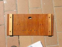
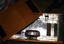
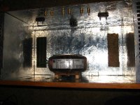
In the mean time my new test box is comming along nicely, Just need to finish the roof. The finnish isn't perfect as it is just a testing box which would allow me to reach the amp boards for measurements etc... the width is standard 19 rack equipment width so I can just stack stuff under it when I'm done. Still need to make a plan for feet or lifting the bottom off the ground so air can get under it. There are vents on the case bottom, and there will be some in the same position, on the lid.
THe face is made from a 4x1/4" plank glued up, the rear is some cherry veneer board with a bit of skeleton from cutoffs from the face, and the bottom is some hardboard, everything is foild coated, I guess if it is good enough for my signal generator, it is good enough for the amp.
THe face is made from a 4x1/4" plank glued up, the rear is some cherry veneer board with a bit of skeleton from cutoffs from the face, and the bottom is some hardboard, everything is foild coated, I guess if it is good enough for my signal generator, it is good enough for the amp.
Attachments


Last edited:
a good VI limiter should protect the amplifier from some/many forms of abuse.Can you expand on this some? I was just wanting to build a heavily biased amplifier that could maintain the same rated power into both 8 and 4 ohms loads. I'd like to have just one amplifier instead of building one for each impedance of speak I own. I own both 8 and 4 ohm speakers.
A bad VI limiter will prevent an amplifier properly passing an audio signal to the next stage. That's what I meant by
allow all valid audio signals to pass to all valid audio loads
The VI limiter controls the device dissipation (limits current) while monitoring both Ic and Vce. The device protection must be set up to use as much of the device temperature de-rated SOAR that is available, so that early triggering of protection does not current limit a "normal" Audio transient, however short or long.
Why do you need this, If the amp can drive 4ohms it can drive 8 ohms...
jlh, if you go back a few posts you will find a link with a description of the circuit operation, protection can in theory be removed... if you kow which parts they are...
Because if the amp is designed only to drive a 4 ohm load the rail voltage will be too low to deliver the same amount of power into an 8 ohm load. Conversely, if it is only biased for an 8 ohm load, it will run out of current before it delivers the desired power into a 4 ohm load.
I'm not really after any kind of protection per se. Audible distortion will be the safety valve so to speak.
Like I said, I own both 4 and 8 ohm speakers and wish to be able to use it on either speaker set. With the heat sink I have, it looks like 12.5 watts per channel is a good target.
I know how to set the bias, adjust the DC offset, and the AC gain balance. The numbers I was having trouble determining were what the rail voltage needed to be, and how high to set the bias. Knowing both these numbers will help me to purchase the correct power transformer. I'd like to get this right the first time if all possible.
What I think I’ve worked up is the correct numbers for both, but would like a more experienced person to check it for me. To make 12.5 watts into 4 ohms we need a peak current of 5 amps. If I understand the Aleph circuit well enough, the CCS should carry half this (2.5A), and the output FETS carry the other half (2.5A). However, I need to probably bias it to something a little bit more like 5.2 amps to be safe.
For the rails we need a peak voltage of 30.984 volts. ( 12.5 watts into 8 ohms) We need to account for Vgs at our bias point, and the voltage drop across the 0.47 ohm source resistors. The IRF640 requires a Vgs of about 4.75 volts to source 1.3 amps. Each source resistor will drop 0.611 volts. So each rail will need to be ((30.984/2) + 4.75 + 0.611) = 20.853 volts. To be safe I’m thinking +/-21V rails. Does all this look correct?
Attachments
Last edited:
Sorry, but you are still not makeing sense (to me).
Lets look at the big brother Aleph 3.
It does 30W into 8 ohms and 60 into 4 and 2.
Going by that route a mini that does 10W into 8 ohms should push 20W or close into 4 ohms. You can't have too much power for a speaker, only too little attenuation on the volume control.
What speakers are these? do they have the same efficiency and power rateing but just diffirent impedances?
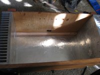
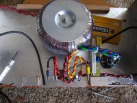
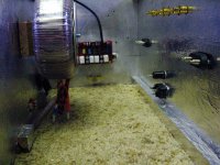
Got a bit more done today in the form of mounting the rectifiers and transformer... Man, I hate working with those fat wires. The rectifiers are hidden by transformer when viewed from the top. Sockets and connectors have been screwed in, and the lid and its vents have been cut and chisseled.
Attachments
Last edited:
Sorry, but you are still not makeing sense (to me).
Lets look at the big brother Aleph 3.
It does 30W into 8 ohms and 60 into 4 and 2.
Going by that route a mini that does 10W into 8 ohms should push 20W or close into 4 ohms. You can't have too much power for a speaker, only too little attenuation on the volume control.
What speakers are these? do they have the same efficiency and power rateing but just diffirent impedances?
Thank you Digits, this is the type of correction I needed. Both speakers are DIY. The 4 ohm ones are 91dB with 2Vrms into them, and the 8 ohm ones are 90dB with 2.83Vrms into them. So, yes for all practical purposes they have the some efficiency, but different impedances. Thanks for your help.
JLH,
Attached is a Excel spreadsheet that can be used to calculate the output in various configuration. Hope this will be useful.
Thank you for the spread sheet. This will help a lot.
As far as I can tell with 8 ohm loads, you are voltage limited, with 4 ohm, you are current limited, with 6 ohm you should see the highest output power.... Which suits me as the Kirkseaters I will use it with until my fullrangers are done, are 6 ohm.
Whish I could afford the second set of PSU caps this month, but I am saveing up for the factory run with the PCB to help encourage people to try their hands at alephs again, but otherwise my case is comeing along nicely now.
I just finished tapping the heatsinks for mounting the boards properly as well as mounting thermal fuse. Tommorrow I need to see if any other parts went to heaven with the FET that desoldered itself, which I assume is a gonner. Then I need it instal the wires, to get it running temporarily, while I get the clipping indicator and the input selection relay boards etched. Hopefully I will have an aleph to listen to again by tommorrow evening. The sansui sounds so muffled compared to the aleph its just dreadfull not haveing it running at the moment.
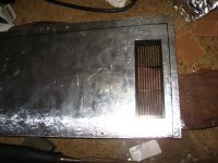
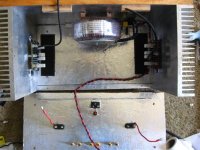
Ok construction picture time again.
I have the mains wire in now, connected to the thermal fuse under the red PCB inthe last pic, from there it goes to the switch wich is connected to the transformer, triac and pre-transformer filter. The rectifiers are also wired in and I just need to add the DC side of the PSU now.
I tested the desoldered FET with my multimeter and it still behaves like a FET, guess we will see when I power it up.
Attachments
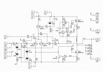
I've got a few questions about Brian's board.
I want to run this from RCA inputs. So I basically don't need:
- R9, Z3 and Z4.
- What's the point of R2 and R3? One resistor is enough. Why 2 with weird values?
Also:
- R5 sets the current for the Zener reference. It seems to me that I can swap this with a single-FET CCS?
- R6 (optional) is to control the DC offset. What value though? It's listed as 'TBD'.
- What do R12, R13 and R17 actually do? They've got different values in all schematics that I see.
I'll be running this from 18-20ish volts, I need to calculate the PSU still and I want to bias it for as much power as I can get out of that. Active cooling should keep the devices safe.
That's about it, for now.
Oh, right, two more:
- R0 Does it really help with anything?
- No Zobel on the output - I plan on attaching one on the speaker terminals, I don't like the idea of running an amp without one. Any objections?
- R0 Does it really help with anything?
- No Zobel on the output - I plan on attaching one on the speaker terminals, I don't like the idea of running an amp without one. Any objections?
I have a weird experience.
When both channels are connected with input, only one channel producing sound.
To get both channels producing sound, I need to cut one of the input ground leaving only the signal line connected to the input while for the other channel, both lines need to be connected to the input.
Anyone with any idea for the solution?
Member
Joined 2002
I have a weird experience.
When both channels are connected with input, only one channel producing sound.
To get both channels producing sound, I need to cut one of the input ground leaving only the signal line connected to the input while for the other channel, both lines need to be connected to the input.
Anyone with any idea for the solution?
post pictures so we can see..
Solved the problem. Just another silly mistake.
I accidentally switched the input connections of the channel. When I plugged in the input, the signal line will be shorted to the ground by the RCA plug, thus resulting only one channel having the input.
I accidentally switched the input connections of the channel. When I plugged in the input, the signal line will be shorted to the ground by the RCA plug, thus resulting only one channel having the input.
I've got a few questions about Brian's board.
I want to run this from RCA inputs. So I basically don't need:
- R9, Z3 and Z4.
- What's the point of R2 and R3? One resistor is enough. Why 2 with weird values?
Also:
- R5 sets the current for the Zener reference. It seems to me that I can swap this with a single-FET CCS?
- R6 (optional) is to control the DC offset. What value though? It's listed as 'TBD'.
- What do R12, R13 and R17 actually do? They've got different values in all schematics that I see.
I'll be running this from 18-20ish volts, I need to calculate the PSU still and I want to bias it for as much power as I can get out of that. Active cooling should keep the devices safe.
That's about it, for now.
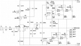
Yes, single ended you can omit Z3,4, but keep R9 and ground the inverting input. If you don't you reduce the gain.
The parallel combination of R2 and R3 set the input impedance. Notice that R10 has that same value on the negative side. Keeping the positive and negative impedances the same helps minimize DC offset.
R5 is part of the CCS. You can swap in another CCS if you want, but the board is set up for a zener controlled mosfet CCS
R12 sets the AC current gain (along with other parts, but varying R12 works.)
R13 fine tunes the bias. Higher values result in higher currents. You can use anything from 30Kish to open depending on your heat sink capability. There is an Aleph 30 schematic around somewhere with a table showing how this resistor impacts current.
R17 sets the current limit for the output devices. You choose the value to provide peace of mind - notice the voltage divider it forms. You'll want to keep the voltage well below the turn on voltage of the bipolar protection transistor at normal currents.
Oh, right, two more:
- R0 Does it really help with anything?
- No Zobel on the output - I plan on attaching one on the speaker terminals, I don't like the idea of running an amp without one. Any objections?
R0 isolates the power and signal grounds and provides ground loop isolation.
If the commercial Alephs didn't use an output Zobel, why do you think this one needs one? It won't hurt the amp, but may impact the sound.
Solved the problem. Just another silly mistake.
I accidentally switched the input connections of the channel. When I plugged in the input, the signal line will be shorted to the ground by the RCA plug, thus resulting only one channel having the input.
I have that T-shirt too.

- Home
- Amplifiers
- Pass Labs
- The Mini-A