Member
Joined 2002
Because it clips pretty easily and my speakers are only 15W jobbies, and pretty much irreplaceable.
I hope I can figure out what I just did, I did the fuse swap, but during testing of offset, an output fet started to smoke it's thermal paste. I pulled out the power cord, then I wanted to see if the fet was properly screwed in, but pulling on the PCB, it came clean off the FET, the bugger desoldered itself.
Sounds like you didn't have it bolted to the heatsink properly, or the heatsink is to small and it wasn't dissipating all the heat that the fet was creating.
Did you use a thermal pad ? was the fet tight against the heatsink ? I have YET to have any issues with any of the alephs i have built all 6-10 hand fulls they have all run 100% fired up perfectly at first power up and etc etc..
No, my sinks are giant for the amp, and it was on properly, I didn't move the boards, since they last played yesterday, I must have bumped something in our out, the case is WAY too small but the sinks are 20 x 20cm blocks. Isolators are TO220 mica wafers.
I was quite surprised by this, as my experience with it up to now has also shown them to be pretty much bulletproof.
Man!!!!, I just realised I don't have any spare 644's, looks like I need to go back to the IRF540's (which I kinda like better as they have more mellow higher registers - I.e. its a system thing, other speakers may sound better with the 644's).
Last edited:
Member
Joined 2002
No, my sinks are giant for the amp, and it was on properly, I didn't move the boards, since they last played yesterday, I must have bumped something in our out, the case is WAY too small but the sinks are 20 x 20cm blocks. Isolators are TO220 mica wafers.
I was quite surprised by this, as my experience with it up to now has also shown them to be pretty much bulletproof.
Man!!!!, I just realised I don't have any spare 644's, looks like I need to go back to the IRF540's (which I kinda like better as they have more mellow higher registers - I.e. its a system thing, other speakers may sound better with the 644's).
There are only a few reasons why the main fets would come off the board,
A your didn't solder them on properly
B your heatsinks are to small
C your fet's were not mounted to the heatsinks properly to help dissipate the heat.
If your amp is clipping that easy then it's probably not setup or built properly, Id look over the construction more. IRF644's ? why are you using those and not the 250's like it was designed for ?
Did you use any thermal paste between all the layers of the fet ?
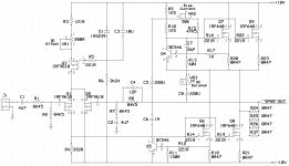
Post a picture of your setup ? and how you have constructed it ?
I will let you know how much it drops when I am done adding the pre-transformer fuse and removed the ones between mu PSU and the amplifier boards. I need to measure it anyway to set up the clipping detector. My guess is you will be good on a 15V transformer, I think they use the 18's for the 25W alephs.
Thank you. I will continue to watch this thread for you post.
After working through a few calculations, I think I understand how to calculate the correct rail voltages and bias current along with the heat sink requirements. If somebody would be so kind to tell me if I did this correctly that would be great.
I have a single heat sink that is 10” X 16” X 3” and is said to be rated at 0.13125 C/Watt. I’d like to keep heat raise to +26 C above ambient. So this would limit me to about 200 watts of dissipation for both channels combined. The way I’d like the amp to work is to be power limited due to rail voltage into 8 ohm loads, and then current limited due to the bias current into 4 ohm loads. Originally, I thought I could do 15 watts, but I think that is pushing it too much. Below are my calculations for the bias and rails for 12.5 watt output.
Bias for 12.5 watt into 4 ohms
SQRT(12.5 Wrms X 4 ohm) = 7.071 Vrms
7.071 Vrms/4 ohms = 1.768 Arms
2 X 1.4142 X 1.768 Arms = 5 Ap-p
The upper devices will carry 2.5 Amps and the lower devices will carry 2.5 Amps. I’m looking at using two pairs of IRL640 FETs per channel. Looking at the Id vs. Vds graph it looks like I’ll need Vgs to be 4.635 volts for each FET to carry 1.25 amps each.
Rail for 12.5 watts into 8 ohms.
SQRT(12.5Wrms X 8 ohm) = 10Vrms
2 X 1.4142 X 10Vrms = 28.284 Vp-p
(28.284 Vp-p/2) + Vgs = rail voltage, so rails would be +/- 18.767 Volts. What about the voltage drop across the source resistors? Do I need to account for this too? If so, then the rails would need to be about half a volt higher with the standard 0R47 source resistors.
Dissipation would be (2.5A X 18.767V X 2) = 93.835 Watts per channel and 187.7 Watts total. Temperature raise should be 0.13125 C/Watt X 187.7Watt = +24.635 C. Looks okay to me.
The best thing to do at this point is to stop, sit down, and come up with a plan...before doing anything else.
A 20-0-20 transformer is going to put you into an Aleph 3, which translates as 25W per channel. It uses two pairs of devices per channel. If you intend to stick with the Mini-A circuit at those rail voltages, you're going to be looking at some pretty serious warmth for a single pair of devices if you bias them at Aleph 3 levels. You will want to lower the bias.
I'm not clear how you've decided that 10W or so from a Mini-A is not enough, 25W from an Aleph 3 is too much, but 15W is just right. However, the rail voltage for 15W isn't that much higher than what's required for 10W. You'll need to reduce the rail voltage coming from that 20-0-20Vac transformer, either by regulating the rails or using resistors in a CRC filter. Either way will create a fair amount of heat.
I'm also a little hazy as to why you want to increase the bias, especially since you say your speakers are 8 Ohms. Yes, it will make things sound better, but it also increases the amount of heat you have to dissipate, which kinda starts being a problem. You don't specify what current the transformers can deliver, but if they aren't up to delivering the current, you're going to have problems there.
Amplifier design goes like this:
--Pick a target load. In your case, you're saying 8 Ohms.
--Pick a target power into that load. You're saying 15W.
--You then calculate the rail voltage you'll need to swing that much voltage (remembering to subtract Vgs for the output devices--in this case, rough it off at about 4V ea. or 8V total).
--Using the power you chose and the load, calculate the current you'll need. A push-pull output stage will deliver twice its quiescent bias, so you only need to bias for half the current.
--Multiply the rail by the bias current to see how much heat you'll dissipate.
--Choose the device (with one eye on how much power it can dissipate--this is heavily dependent on the case style) and play with what-if scenarios to decide how many you'll need in order to dissipate the heat safely. Nelson routinely runs things hotter than I do. He will tell you that you can run up to 50W per device if you have sufficient heat sink capability and are willing to run a little risk. Note, however, that he usually runs his outputs closer to 20-25W ea. I regard 35W/device as about the limit and generally run 25-30W ea.
--Choose your heatsink according to the maximum temperature you're willing to accept. Nelson accepts grill marks on his hands. I like to be able to leave my hand on the heatsink indefinitely.
Just sit and think for a while. Then act. Not the other way around.
Grey
Attachments
My best guess is that I must have wriggled the fet loose from the sink when I pulled of the output faston connector. DC offset was fine till it smoked. The amp has been working fine for months now. Decided last night I will make a bigger box, that setup is way too cramped for safe working. I never designed the current case to also hold a transformer. Think I'll just build one of Hugh Dean's AKSAs in the small box for the wife to have sound at the TV... hell she could even use the old sansui that is standing there.
Oh, yes, I use thermal paste on both sides of the insulator.
Oh, yes, I use thermal paste on both sides of the insulator.
Last edited:
Member
Joined 2002
My best guess is that I must have wriggled the fet loose from the sink when I pulled of the output faston connector. DC offset was fine till it smoked. The amp has been working fine for months now. Decided last night I will make a bigger box, that setup is way too cramped for safe working. I never designed the current case to also hold a transformer. Think I'll just build one of Hugh Dean's AKSAs in the small box for the wife to have sound at the TV... hell she could even use the old sansui that is standing there.
Oh, yes, I use thermal paste on both sides of the insulator.
wiggled the fet loose ? if you can wiggle your fets loose then you don't have them mounted properly or tight.
Use a good strong machine screw, also use a washer overtop so you can distribute the pressure over the fet evenly s its not cockeyed..
example, of this,

Last edited:
Yeah, I cut some corners, and used only 2 screws and a standoff to mount, so it was pretty easy to move stuff around with a little force....
Member
Joined 2002
Yeah, I cut some corners, and used only 2 screws and a standoff to mount, so it was pretty easy to move stuff around with a little force....
sloppy work just proved to you that it always fails..
Found the culprit on my circuit.
It's the 0r33 resistor near the FET. Smoked when I had reversed polar earlier.
Luckily the FETs survived.
Guys, make sure you have better precautions when testing the circuits.
Don't repeat my dumb mistake 🙂
It's the 0r33 resistor near the FET. Smoked when I had reversed polar earlier.
Luckily the FETs survived.
Guys, make sure you have better precautions when testing the circuits.
Don't repeat my dumb mistake 🙂
Member
Joined 2002
Found the culprit on my circuit.
It's the 0r33 resistor near the FET. Smoked when I had reversed polar earlier.
Luckily the FETs survived.
Guys, make sure you have better precautions when testing the circuits.
Don't repeat my dumb mistake 🙂
variac / lightbulb in series 🙂
I make sure I've got functional RCDs and safety goggles. The rest .... well 🙂 The rest is the fun part.
I make sure I've got functional RCDs and safety goggles. The rest .... well 🙂 The rest is the fun part.
Watching the smoke is part of the 'fun'
To be fair, I've only smoked 1 SMD opamp so far. Nothing too spectacular. And my forearm once. Let's hope the Mini-A continues that trend.
Edit: My forearm twice. Once I smoked it with a very hot soldering gun.
Edit: My forearm twice. Once I smoked it with a very hot soldering gun.
Member
Joined 2002
To be fair, I've only smoked 1 SMD opamp so far. Nothing too spectacular. And my forearm once. Let's hope the Mini-A continues that trend.
Edit: My forearm twice. Once I smoked it with a very hot soldering gun.
ouch, did that when i was 7 🙁 hurt 🙁 never did it again tho.
No more smoking Alephs guys 🙂
Try a blob of solder on your inner thigh from soldering with shorts on.
I've just got out of the garage, finnished cutting and glueing up a plank of meranti to make a face on the new test box. (Coffin - 19" rack width by 8 inches high).
I've just got out of the garage, finnished cutting and glueing up a plank of meranti to make a face on the new test box. (Coffin - 19" rack width by 8 inches high).
Last edited:
Watching the smoke is part of the 'fun'
OK, but... what is then "fire"?
Arthur Brown "Fire":

"...
Fire, to destroy all you've done.
Fire, to end all you've become.
I'll feel you burn!
You've been living like a little girl,
in the middle of your little world.
And your mind, your tiny mind,
you know you've really been so blind.
Now 's your time burn your mind,
you're falling far too far behind."


Never mind...
 & for fun !
This protection will not allow all valid audio signals to pass to all valid audio loads.I plan to run just enough current to maintain 15 watts into 4 ohms. So, I'll be voltage limited at 8 ohms, and current limited at 4 ohms.
This protection will not allow all valid audio signals to pass to all valid audio loads.
Can you expand on this some? I was just wanting to build a heavily biased amplifier that could maintain the same rated power into both 8 and 4 ohms loads. I'd like to have just one amplifier instead of building one for each impedance of speak I own. I own both 8 and 4 ohm speakers.
- Home
- Amplifiers
- Pass Labs
- The Mini-A