Thanks Bob! I now have the final parts on order and I'll be working on putting this together, finally.
I normally install a ground-loop breaker of a diode bridge, power resistor and a cap. I guess I'll omit R0, unless I find a reason to install it.
The Zobel is just a precautionary measure, really. I'm not too bothered about miscalculating it so much that it eats my highs 🙂 I'll see how it goes, it's easy to remove from the output terminals anyway.
Oh, what about the magical R6, anyone? I did the maths for the rest to get what happens where (I think I'm fine now) but that one is still a mystery to me.
I know I shouldn't need it with matched input pair and resistors, but my obsession with 0-volt offsets isn't exactly rational 🙂
I know I shouldn't need it with matched input pair and resistors, but my obsession with 0-volt offsets isn't exactly rational 🙂
I don't think my baords have that R6 in, the R8 above it, can be used to fix offset which will vary depending on the output fets you use. There was about 50mV diffirence between IRF540 and IRF644 with the same resistor setting there before adjustment. You have to run the amp to the point where it reaches equalibrium temperature and the temperature starts tracking the ambient, then do your offset adjustment, as the offset keeps dropping slowly as it heats up, if not it will just overshoot into negative DC offset.
I've just recently lined up a purchase of some Exicon 10P16 TO-3 lateral mosfets. What to do with a bunch of same-sex devices? One thing might be a turned-around version of the Mini-A with n-channel input stage and p-channel outputs. I have some tunnel-style heat sinks drilled for TO-3 packages, so that would be another excuse to gin up a hot little amp. Comments? The laterals have less transconductance than vertical devices, but I may try biasing the input stage hotter for a little more transconductance there.
Hey my baby is playing again, believe it or not, the FET that desoldered itself is still alive and kicking. Did nearly have an issue with connecting the traffo primaryout of phase, the thermistor kicked in and saved the day when I switched the amp on the first time (after I bypassed the fuse to see why the thing just wasnt powering on). Also the hum is now completely gone, like nothing, zip nada, dead quiet.
I'll post pics as soon as I get new batteries, I did actualy buy some but they were duds, many expletives was shared this afternoon. This is one tough design.
I'll post pics as soon as I get new batteries, I did actualy buy some but they were duds, many expletives was shared this afternoon. This is one tough design.
Hah, stole the decoder's remote batteries....
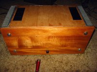
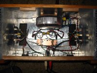
Ok here are the pics, the PSU part is still a bit raw looking as I just used a pair of through hole caps for the second bank, this will be replaced with a set of can types like the first.
Also it is just a test platform, so finish is not of the greatest importance.
Although it is fullly working, a few components still need to be added like the clipping indicator and status LEDs, as well as the relay bank and controls.
the reason the power cord snakes around the side is because it attaches to a thermal fuse.
So far it is dead quiet, and the fixing of whatever was causeing the hum, has improved the sound quality by quite a margin again. Imaging is almost holographic, and you get a crystal clear image of where istruments (mics) are placed.
Oh, yeah, I still need to finish the lid.
Attachments
My Aleph is having speaker pop when switched off. I have read about the capacitor discharge could lead to this.
It's not really a big deal but quite irritating whenever I switch off the amp.
Should I use speaker protection?
It's not really a big deal but quite irritating whenever I switch off the amp.
Should I use speaker protection?
It's the easiest way to prevent on/off thumps, I think. I use protectors designed to switch with a few secs On delay and to trigger immediately on loss of *AC* power. So both On and Off thumps are removed. Plus, I get DC protection on top of that.
You can get decent protectors on ebay, already assembled, for a reasonable price. No need to go overboard.
You can get decent protectors on ebay, already assembled, for a reasonable price. No need to go overboard.
I have a speaker protection from ebay but it requires another transformer to power it.
1 set DIY Speaker protection assembled finished board | eBay
The main transformer could blow the circuit in no time with the large current.
I have a really tight space in my chassis so I need to find a really small transformer for the protection circuit. Do you think what should be the least acceptable current needed to run the protection circuit?
This circuit has its own rectifier and regulator as far as I can understand from the description. Does it come with schematic? If the relays are open when the board is off, which is the usual set-up, you should be able to power it up straight from your transformer. It only consumes as much current as it's needed to keep the replays closed, the size of your transformer doesn't matter.
I think there is a problem with the circuit. I tried it with a 15VAC transformer and the transformer was heated up and vibrating when the circuit is powered on.
Unfortunately I don't have the schematic for the circuit.
BTW, I have tried the circuit with the main transformer but the rectifier couldn't stand the current. The PCB track was peeled off.
My mistake for not reading the datasheet of the rectifier before powering up.
Unfortunately I don't have the schematic for the circuit.
BTW, I have tried the circuit with the main transformer but the rectifier couldn't stand the current. The PCB track was peeled off.
My mistake for not reading the datasheet of the rectifier before powering up.
It sounds like something was really wrong with the wiring. Or the rectifier wasn't installed right, which would give you a lot of grief.
I bought it as assembled kit. From the layout, I believe it was assembled perfectly.
The circuit even worked when powered on but the transformer was vibrating.
I think I have fried the rectifier which has a 1A current limit.
My main transformer is rated at 9.38A.
The circuit even worked when powered on but the transformer was vibrating.
I think I have fried the rectifier which has a 1A current limit.
My main transformer is rated at 9.38A.
Member
Joined 2002
I have a speaker protection from ebay but it requires another transformer to power it.
1 set DIY Speaker protection assembled finished board | eBay
The main transformer could blow the circuit in no time with the large current.
I have a really tight space in my chassis so I need to find a really small transformer for the protection circuit. Do you think what should be the least acceptable current needed to run the protection circuit?
Speaker protection on a aleph mini ? what is the world coming to.. You sir, just ruined a great aleph amplifier by attaching it to a cheap piece of Chinese CRAP!
Speaker protection on a aleph mini ? what is the world coming to.. You sir, just ruined a great aleph amplifier by attaching it to a cheap piece of Chinese CRAP!
I was considering that too.
On the second thought, I would just ditch out the speaker protection and try to live with the pop 😉
If your amp is optimaly set up there is no pop.
My new case with the same PCB as the old one, with only a more optimised groundstar arrangement totaly took care of the pop off. Now there is only a soft fuzzing out similar to a typical class ab.
PS, get a decent rectifier or two, you are looking at 15A or higher pulses.... and close to 4A RMS.
My new case with the same PCB as the old one, with only a more optimised groundstar arrangement totaly took care of the pop off. Now there is only a soft fuzzing out similar to a typical class ab.
PS, get a decent rectifier or two, you are looking at 15A or higher pulses.... and close to 4A RMS.
Last edited:
Member
Joined 2002
I was considering that too.
On the second thought, I would just ditch out the speaker protection and try to live with the pop 😉
thermistors are 2$ each but 4-6 in parallel and a cap on the ac input, it will slow the inrush current.
Also mmight want to do a clc psu or put bleeder resistors across the caps to speed up the discharge on them.
Personally, never had any pop or any hiss, then again i used a crc psu..
Jason
Yep, we have that in common, I am useing CRC too. Even when I had the off pop I never had a power on pop, the off pop was quite loud before tough.
Why would you want to parallel the thermistors? This nearly removes their usefulness. Check schematic on last page of F5 construction manual for option for how to use CL60.
Uriah
Uriah
Member
Joined 2002
Why would you want to parallel the thermistors? This nearly removes their usefulness. Check schematic on last page of F5 construction manual for option for how to use CL60.
Uriah
Series, sorry, my bad.
- Home
- Amplifiers
- Pass Labs
- The Mini-A