HTML:
thanks for the tips.
I use preview sometimes. I did not realise it would allow my computer to "hold" a copy of a lost post.
It can because it allows your browser to navigate back and forth without losing your input in it's form fields.
Once you submit to the forum, your browser is being told to reset those fields (as the editing session is closed), for that people don't accidentally resend the same posting.
Is ^+A ^+C shift plus A and shift plus C (shortcuts for ?)
It's Ctrl+A for selecting all and Ctrl+C for copying the selection.
Those are the very same commands you'll find in the Edit menu of your browser window and hitting the keyboard shortcut sequence is equivalent to selecting the two commands in the drop down menu. But the keyboard is way quicker and more convenient, as it is where your fingers are at anyway. 😉
With your input cursor being in the editor of the forum browser window, this command sequence will automatically select everything you're about to send, including quotations and markup code like images and links.
In case of a forum hickup (or a browser crash), you're still left with your whole posting in your computer's clipboard, ready for pasting it (using Ctrl+V or the Paste command in your Edit menu) into a fresh forum window.
The usual shortcut symbols are:
⇧ for Shift (upper case)
⌃ for Control (modifier key for commands)
⌥ for Option (as in alternative character/command, not to be confused with AltGr)
⌘ for Command (or the ⊞ Windows or ◆ Meta key, respectively)
The former shortcuts, before they were called shortcuts, were far quicker.
Yes, those terminal and workstation keyboards had their own set of keys for editing purposes. 🙂
Why did Microsoft copy those silly folk @ Apple and adopt mouse + icons?
To think Apple invented it is like saying Apple invented the smart phone. 😉
And to think they are silly is overlooking the danger they pose nowadays, due to their smartness... 😡
Everyone salvaged on Xerox back then...
Safety is improved (I'll not say maximised) by isolating the gear under test. The scope still being PE grounded and that way the Scope and the Scope Probe are safe to touch.
Agreed and noted. 😉
I was probably thinking of work I once did on the primary side of a power supply... 😀
Sometimes there is a switch on the probe to go between 1x voltage and 10x voltage. You want to make sure that if you are measuring high voltage for your scope that you have the setting on 10x.It says 300V CAT II
or preferably an unswitched 100x high voltage probe.Sometimes there is a switch on the probe to go between 1x voltage and 10x voltage. You want to make sure that if you are measuring high voltage for your scope that you have the setting on 10x.
Thanks Digits.
Why did Microsoft copy those silly folk @ Apple and adopt mouse + icons?
The former shortcuts, before they were called shortcuts, were far quicker.
PS if you look at the front of the keys on your keyboard, you will likely see the functions printed on them, appart from the 3 I mentioned there are also Ctrl U for undo, ctrl B for bold, , control I for italic, ctrl F for find and ctrl P for print.
I miss how efficiently DOS systems used the hardware, only thing I ever seen come close was BEOS.
I have no intention of fiddleing on the primary side of the transformer with my scope.
Last edited:
So this thread got a little quiet, I was very busy and am operating on one hand due to arthritis at the moment. Nevertheless I received the first set of PSU caps today.
I also matched the 10 Fets I bought for the dif pair. Got one perfect match, and one that is about 0.9mV appart for the second channel.
Now if I had the foresight to buy lug spades for the caps I could power up the first channel. I hope the IRF540 outputs I have till august won't burn out or something. The vishay irf644's is due the second week of aug I think, but I need to get this baby tested now so I can get it to the factory to make some boards for the guys who asked.
I will upload pics of the rig a little later, everything is ready and mounted on test heatsink, just need to make a bulb tester. I think everything will be fine though, I preset the trimpots etc...
Hi, do I need a load connected in order to set up bias?
I wired everything up, nothing smokes, but it is only drawing a few mA of current, and ahs about 13VDC on the output... 🙁
Neither the bias (measured with the meter connected in stead of fuse) nor offset changes with turning the trimpots. I do have the input shorted.
I have also tried to measure DC over the power resistors, but get 0V instead of the half a volt or so expected.
I get the correct voltage by the zener, rail - 9.1V, Rails are 16.8V with no load connected to the output.
And I get 3.5 volt at the junction between the CCS and the diffirential pair.
Any help or testing procedures would be welcomed.
I suspect the problem lies in the output section.
Last edited:
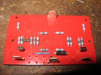
Ok, found it, stupid eagle error, one wire in the schematic was split as two names, so there was no connection between two sections. It was the wire that connects below the first fet of the input pair feeding the gate of the bottom output fet.
Things look cool now measurement wise. DC below what my meter can read, bias seems to be about 1.2A, and rails at +/-15.07V
Not sure if I should connect a speaker as I only hae the first half of the CRC PSU in place, there is bound to be some audiable ripple on the output.
Now for the bad news, I am going to have to incorporate another wire jumper to fix this, as there seems no other way to get the two points connected. I simply soldered in a wire for now, but this would not do for shareing. So, I'll try to fix that one thing up this weekend and then we can talk factory next week.
For now I am feeling very relieved and happy.
Last edited:
This post, the link works for me though.....here is what we have so far....
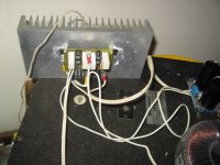
Ok, this is what itlooks like on the test sink.
I did seem to make an error measureing DC, as ther is about 15mv of DC on the output, nothing I would worry about though.
It starts up and shuts down without thumps or pops, is totaly humfree and totaly hiss free on my 100db/W test speaker. A 15W fullrange Goodmans axiom.
Best of all is the PSU is just 2 sets of 10000uf caps in parallel, no R in between.
With the small sink it gets about 32C above ambient, which is right as it is about 1C/W. The final sink is 0.8C/W and will be augmented by 10mm aluminium front plate and 3 or 4mm in the rear.
Appart from the Precision one, I have not heard an amp with this kind of resolution in the mid to upper registers before. Hollow instruments, sounds, well, hollow. I even listened to some of my wife's music I can't stand, just because it sounded so diffirent. Bass is strong and controled.
While at thesame time retaining a smooth warmness (in sound) rather than sterility. Think I will slap the other channel together today, (luckily I prematched and marked the resistors for it 🙂 .
Ooh and I might even connect it to the scope if I can figure out the testing procedure.
Attachments
Last edited:
funny - almost finished typing answer what's possible to check ..........
seems that you also messed measuring current through stages , at least looking at fact that amp is functional suddenly

seems that you also messed measuring current through stages , at least looking at fact that amp is functional suddenly
I only innitialy measured current between PSU and amp, and got about 20 or 30mA, which I think the front end was useing, as the front fets were a little above abient temp after an hour or so, while I figured it out.
There was simply no drive to the second output fet. Overall it seems pretty stable now, no fluctuations in outputs, temperature is rock solid too. Allthough I wouldn't try and run it on that sink when it gets up to 40C here.
There was simply no drive to the second output fet. Overall it seems pretty stable now, no fluctuations in outputs, temperature is rock solid too. Allthough I wouldn't try and run it on that sink when it gets up to 40C here.
lol, wife is still in bed, willcheck as soon as she gets up, or there is hell when I make noise. At last check after the repair, Iq was 1.25A.
Ok, yeah, still 1.25A.
I have a question (again).
The IRF644 has an RDS of 0.22 ohm, whereas the 540 has RDS of 0.44 ohm.
Should I change the power reistors to 0.33 ohm to stay the same?
I have a question (again).
The IRF644 has an RDS of 0.22 ohm, whereas the 540 has RDS of 0.44 ohm.
Should I change the power reistors to 0.33 ohm to stay the same?

- Home
- Amplifiers
- Pass Labs
- The Mini-A