Just a busy day. 😉
At the risk of repeating myself, but...
Oh, and praise and admiration will come upon you as soon as you find a purpose for C4 (sitting there, looking good) and provide a flawless implementation for this very use without moving that cap even the slightest bit. 😛
While you're at it, the traces between pins three of both output devices and their corresponding power resistors are still thin. 🙄
Cheers,
Sebastian.
PS: What happened to balanced inputs? That was my original reason for chiming in on this thread. 😉
At the risk of repeating myself, but...
sek said:I think you should stop worrying and start prototyping.
Oh, and praise and admiration will come upon you as soon as you find a purpose for C4 (sitting there, looking good) and provide a flawless implementation for this very use without moving that cap even the slightest bit. 😛
I guess you don't want to see the version with the bias trimpot then?
While you're at it, the traces between pins three of both output devices and their corresponding power resistors are still thin. 🙄
Cheers,
Sebastian.
PS: What happened to balanced inputs? That was my original reason for chiming in on this thread. 😉
Hi , OK, I'll fatten up the traces... I also thought about paralleling those caps, that IS what you meant?, but not sure how the increased capacitance there will affect the circuit.
I have enough parts for a prototype, but I forgot to get the zener... I was wondering if I could just connect a 5V regulated supply there were D1 and R7 would meet on the schematic, to test things, otherwise I need to wait for RS to deliver, they actualy dropped my ztx450 next day, on Thursday, 75km away, 5 tiny transistors in almost a shoebox.... very bad mkaaaay.
I also now have a signal generator, so with a little aid I can put my scope to use setting things up...
PS I simply don't know how to add the unbalanced input, which is why I asked for help with it. It is not a dealbreaker for me as I have no balanced sources, and I'm unlikely to ever be able to afford any.... 😀
I was holding out on the prototypeing as I have been doing lots of incremental protos lately, for once I'd like to get it perfect, first try.

Hi , OK, I'll fatten up the traces...
Nice. 😉
I also thought about paralleling those caps, that IS what you meant?, but not sure how the increased capacitance there will affect the circuit.
It's not what I meant, but it's not the worst of ideas. But only if you make both C1 and C4 470uF and wire them anti-parallel (so as to form a bipolar capacitor of 235~220uF).
What I was actually wondering: have you really not once considered to leave it out?
I have enough parts for a prototype, but I forgot to get the zener... I was wondering if I could just connect a 5V regulated supply there were D1 and R7 would meet on the schematic
Good point, what schematic actually? I'm afraid I lost track of the actual circuit you refer to. We've seen a couple throughout this thread.
I simply don't know how to add the unbalanced input, which is why I asked for help with it.
I'm going to attach the one I used, although there are better ways to do it (depending on your original circuit).
It is not a dealbreaker for me as I have no balanced sources, and I'm unlikely to ever be able to afford any.... 😀
I build mine myself. It's cheaper than buying good unbalanced. 😉
I was holding out on the prototypeing as I have been doing lots of incremental protos lately, for once I'd like to get it perfect, first try.
I'm always amazed at how much further insight I gain by finally getting my hands onto actual hardware.
And prototypes can be tweaked to suit, so no need to make a second one unless the first one is too far off. But from my experience, the doing it right the first time attitude is something one should attempt after mastering the craft. Personally, I'm not there yet...
Attachments

Yeah, about the caps, with just a hole there, it looks ugly, but its totaly up to the assembler to put it in, or not... I do not like antiparallel electrolytics at all, based on some experiments I did over the years.
But, even if I had no problem with it, it would realy mess up the top of the boards, especialy if I try to keep the orientation of the caps the same to reduce problems for builders. There is just no place for the traces left.
..........................
My bad about the component numbers, I treid sticking to the original numbers, but it would apper during editing I took my eye on that. The 5V point I was refering to was where R11, R12 and the zener meets on your schematic. There is no room for saying OOPS after sending boards to a factory unless you have deep pockets.
.......................
I'll look over the balanced thingy.. seeing way too many parts there to fit into the current project without a near restart. Also what about those resitor values changeing so much from the unbalanced model... wouldn't that mess up trying to use an unbalanced source?
The only thing I have that I might be able to get balanced outputs out of is my DVD player, as it has a digital output, but I'd have to get around to actualy building a DAC....succesfully 🙂
..................
Lol it is not a craft you can master, its a black art. But seriously, its a bad idea pumping out PCB while I am still hovering over the layout in software. I am a bit of a perfectionist, and working with patched PCBs just drives me nuts, and then I HAVE to make a new PCB, which conflicts with my not likeing to waste stuff, and then I go more nuts, and that is dangerous.
I do appreciate all your suggestions and help though, as you can see I wait each day for your response 🙂
Oh and its a forum, anybody else have anything to say?
Last edited:
I do not like antiparallel electrolytics at all
Aaah, me too! I screwed up there and got the term (foreign language...) wrong, sorry. I meant to say in series, back to back.
But, even if I had no problem with it, it would realy mess up the top of the boards
In your last layout mod you actually made room for that idea all by yourself by moving the high current trace above that cap. From over here I don't see how any component would have to be moved or rotated at all.
My bad about the component numbers, I treid sticking to the original numbers,
No, you're right, I was just uncertain who's schematic you referred to.
I used my own component designation pattern, as I didn't derive directly from GR's original schematic but collected various suggestions from different sources.
It's just that once you consider differential input, input protection, HF feedback, etc., you easily end up using nearly as many parts as an actual Aleph... 😉
The 5V point I was refering to was where R11, R12 and the zener meets on your schematic.
That zener drops a portion of the supply voltage and forms a voltage reference together with it's series resistor (current limiter, to ground). This drives the mosfet gate accordingly.
If any, you could try supplying the respective voltage difference (depending on your planned supply voltage) to that node.
seeing way too many parts there to fit into the current project without a near restart
I agree, although only two additional resistors (and some component value changes) are required. I added protection circuitry, as mentioned above.
But a balanced input amp would deserve a layout approach on it's own.
wouldn't that mess up trying to use an unbalanced source?
It would if you were to switch source type without switching impedances. It would be up to everyone's own purpose to wire it one or the other way.
There is no room for saying OOPS after sending boards to a factory unless you have deep pockets.
Which is why I suggest to consider prototyping. 😉
If your first run shall be your only run, then you'd have to live with whatever it turns out...
I am a bit of a perfectionist, and working with patched PCBs just drives me nuts
I would say that of myself, too. I've been there and went that way. Fortunately I kept those boards for myself and don't have to show them to others. They work and sound fine, though. 😉
I'm not suggesting patched production PCBs, I suggest patching a prototype PCB before going into production.
Making one prototype (one single board only, i.e. at home, as you expect others to do anyway), patching this in multiple iterations (reusing that very one PCB until it fails) until you're satisfied, then finalising your layout and going into production might leave everyone with a better result overall. And on top of that, it's unlikely that you'd have to apply more than one or two changes, so one PCB should suffice.
I'm not suggesting anything about the quality of your project here, it's just general experience (and common engineering sense) that a trial run should be considered. Nobody says you can't reuse the prototype layout for the final production without ever applying changes, should it turn out to be perfect right away.
Oh and its a forum, anybody else have anything to say?
Yeah, anyone? 😉😉😉
Last edited:
I agree on just about everything I think, except the capacitor, I would need to rotate one as far as I can see, so it will be diffirent from the other 3...
The printed press and peel is allready infront of me, I'm just busy makeing a small stand thingy for my new scope and signal generator 😀
I might as well throw the pcb through the tablesaw so long as i want to start on that tonight. including the erroneously parallel connected caps 😛 (i'll jut cut the trace and pretend its not there).
I ordered the transformer so long, not sure if it is localy stocked or ex UK, I do have a 50VA 12VAC EI core around here somewhere I can use to test basic functionality on one channel so long, untill the big boy pitches up, a nice fat 225VA jobby.
Last edited:

BIG BROTHER IS WATCHING YOU!!!Oh and its a forum, anybody else have anything to say?


Joke apart!
Congrats guys to your efforts & my best wishes!
Hope to here good news very soon!

I agree on just about everything I think, except the capacitor

including the erroneously parallel connected caps 😛

(i'll jut cut the trace and pretend its not there).
😀
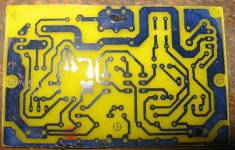
Ok, ready for etching. Oh yeah, gotta cut those traces still..
And use some permanent marker on the thin and fuzzy spots. 😉
Way to go!
Lol I have something even better than a marker, my wife's nail polish!!!!
Definately going to make the bottom trace fatter as I made provision for adding axial caps for decouping the output pairs.
Definately going to make the bottom trace fatter as I made provision for adding axial caps for decouping the output pairs.

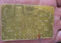
Buggers didn't pack my power resistors, and I still need to figure out some kind of jig to match the fets for the front, I only have 10, hope I can get 2 reasonable sets out.
Also have to find my 1.5mm drillbit for the spades' holes.
And then waiting on the rest of the parts like the transformer etc, and working on the PSU's so long.
Also have to find my 1.5mm drillbit for the spades' holes.
And then waiting on the rest of the parts like the transformer etc, and working on the PSU's so long.
Attachments
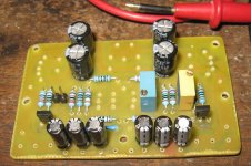
Heh, I was caught out a little with the power resistors, the size is correct, but I didn't notice the pins are a little offcentre.
I could manage to fit them all, but spaceing is a bit off from the innitial plan, so I will need to update that eagle package to make it perfect.
I could manage to fit them all, but spaceing is a bit off from the innitial plan, so I will need to update that eagle package to make it perfect.
Attachments
Good to see you're getting along with your project. 🙂
Thank god you made a prot... ah, never mind. 😀
I will need to update that eagle package
Thank god you made a prot... ah, never mind. 😀
Last edited:
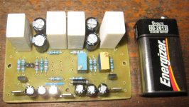
yeah, its not a total dealbreaker, it can be made to work, like I did by just rotaing them till they all fit., thing is if I adapt them to the offcentre package, then that means everybody would have to get the Tyco ones that are offcentered.
If they perform the way I intend for them to work, i.e. stay pretty cool, then its perfect. A cursory overview says it they will see about 1W dissipation, but I used a 5W package.
I always make prototypes before sending stuff to the factory.
Now it just needs a 2 resitors, the FETs, which someone said they would help me with a plan for a jig to match, and the PSU.
Last edited:
Check the attachment for the matching plan. I found it at Design and Construction of an Aleph P Ver. 1.7 Preamplifier. I built a jig using an IC socket with these spring-like contacts so I could easily swap the FETs in and out. First measure them individually, then find pairs using an Excel sheet or raw brain power.
Attachments
- Home
- Amplifiers
- Pass Labs
- The Mini-A