Ok, yeah, still 1.25A.
I have a question (again).
The IRF644 has an RDS of 0.22 ohm, whereas the 540 has RDS of 0.44 ohm.
Should I change the power reistors to 0.33 ohm to stay the same?
it isn't related to that
anyway - you can change from 0R47 to 0R33 if you want to increase output bias (Iq)
say that you'll have 1A25 x 0,47/0,33 then
~ 1A78
recheck offset after that
Thanks for that, it gives me another understuanding of the circuit operation.
I finished the second channel today, as well as fixed my car witch ate a clutch slave this morning.... I hate working on the car though... all the wrong tools 🙂
Anyway, I don't have energy tonight to take appart another amp to use the heatsinks so long, I just swaped the new board and the old one on the same old heatsink. BUT I made a few small alterations to the new one, in the form of film bypass caps on the 220uf caps, and one of the sets of small electrolytics at the bottom has also been swapped for a film cap. I would say the improvement is big enough to consider including them on the PCB... or maybe I'm just tired and easy tonight.
So far I am quite happy with the project, it is the easiest soldering boards I made yet, it takes maybe 10 or 15 minutes to complete (after matching components).
I am astounded by the sound, heavy, strong and mature with lots of clarity, air and emotional presence, definately still in the sweet category rather than the clinical reproduction one. It suits my tastes and drivers from the late 50's or easrly 60's very well.
I also like the gain on the amp, driving it to pretty crazy levels on just a first generation ipod shuffle, I got it max volume and it is just within the range of output that the speakers don't start to distort from high output.
Last edited:
I am astounded by the sound, heavy, strong and mature with lots of clarity, air and emotional presence, definately still in the sweet category rather than the clinical reproduction one. It suits my tastes and drivers from the late 50's or early 60's very well.
digits
What are your speakers (inc sensitivity and ohms)?
Cheers
Last edited:
It should be, either way, it seems to run fine so far on just 2x10000uf CC with no R, allthough I plan to use some R when I get another set of good caps.
It should be, either way, it seems to run fine so far on just 2x10000uf CC with no R, allthough I plan to use some R when I get another set of good caps.
I was thinking to use only C filter too. But after some searching I found some 5W 0.18ohm resistors on ebay.
6 x 15000uF for both channel powered with a 2x12V 225VA 9.38A toroid.
I hope that would be sufficient for my dual channel Mini-A 😀
I am useing a similar transformer and so far there is still a little headroom for the R stage voltage drop.
I would use two pairs of your caps before the C, as the first bank sees some massive ripples.
I would use two pairs of your caps before the C, as the first bank sees some massive ripples.
I am useing a similar transformer and so far there is still a little headroom for the R stage voltage drop.
I would use two pairs of your caps before the C, as the first bank sees some massive ripples.
CCRC - sounds good isn't it?
Yeah it should be good, sorry for not answering sooner, My grandma passed away (not totaly unexpected phone call, as she "visited" me). Same thing happened when my dad passed along, her funeral is on his death aniversary... and my mom's birthday, so I have my hands full here).
Yeah it should be good, sorry for not answering sooner, My grandma passed away (not totaly unexpected phone call, as she "visited" me). Same thing happened when my dad passed along, her funeral is on his death aniversary... and my mom's birthday, so I have my hands full here).
Sorry to hear that. My deepest condolence to your family.
Hi guys, I realised I was posting in the F5 thread so getting some data back into this thread... I have added the 10pf cap of the feedback resistor as well as the 1nf cap suggested for the one protection transistor.
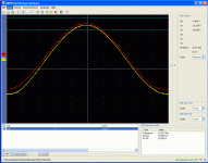
It seems to have fixed the ringing in the sine waves problem. I can get a very nice and clean wave up to 9V RMS into 8ohm now which equals just north of 10W by a bug hair.
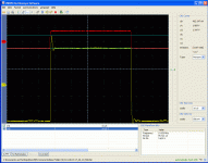
It did not solve the overshoot on the sqare wave issue thoug. There is a 450mv overshoot in the example I attach. any suggestions are welcome at this stage.
Attachments
hmmmm, it seems the square wave thing is realy caused by the lead, I reverted to takeing signal 1 from the amp's input rather than on the other side of the cable at the generator's output, I'm not saying it is definative, but you will see the overshoot on the incomming signal now, so to some extent the amp is only doing what I'm asking.... garbage in, garbage out.
Attachments
Question
Hello everyone, I have a question. Can a stereo Mini-Aleph be converted to use as a mono-block amplifier with a single rca input ? If so could someone please post a simple wiring diagram or schematic ? Any information would be greatly appreciated Thanks !
Hello everyone, I have a question. Can a stereo Mini-Aleph be converted to use as a mono-block amplifier with a single rca input ? If so could someone please post a simple wiring diagram or schematic ? Any information would be greatly appreciated Thanks !
Member
Joined 2002
Hello everyone, I have a question. Can a stereo Mini-Aleph be converted to use as a mono-block amplifier with a single rca input ? If so could someone please post a simple wiring diagram or schematic ? Any information would be greatly appreciated Thanks !
why do you want to ? why not just build 1 channel ?
Becuase I'm looking to build a small pair of mono-blocks like these > Monarchy Audio But using the pcb's I have which are the Chip-amp.com ones. Also would you not get more power running a bridged pair ? And I really like the idea of not having monster size heatsinks... it brings the cost way up and acts as a secondary heat source in the summer.
Last edited:
Pcb
Here is the only site in Europe that I know of > http://www.kk-pcb.com/amps.html He has the Aleph M which may possibly work for the J Good Luck !
Here is the only site in Europe that I know of > http://www.kk-pcb.com/amps.html He has the Aleph M which may possibly work for the J Good Luck !
I don't know if these amps can be paralleled, sorry.
I have been tinkering and listening to my mini for a while now.
The IRF644's finaly pitched up and I have spent a few days listening to them, alot more detail than the IRF540 but also not quite as mellow. Astounding quality though.
Sure glad I installed a trimpot for DC offset adjustment as the 644 produces an offset about 50mV off the zero'd value for the 540.
I do have a little hum on one channel, you need to basicaly stick your head in the speaker to hear it though. I wonder if it is similar to a class A headphone amp I built once which required me to tweak the bias in both channels until I got it quiet.
I did innitialy have a small ground loop hum which was killed easily by connecting the input grounds to each other behind the sockets... the hum left after that is only a tiny fraction and only on one side. It could be due to the extreme proximity of the transformer too, I am just useing a temporary case with enough heatsinking, but it is tiny inside, maybe 20 x 20 cm.
- Home
- Amplifiers
- Pass Labs
- The Mini-A


