Enter a load resistance that will draw the same current that you intend to use as bias current. Good old Ohm's law. If you want 1.2A at 16V, use 13.3 ohms.
What would be "good" values for the ripple voltage? With the parts i have (15mF / 330mR(3W) / 15mF) i´ll get about 100mV at 1,2A bias setting...
😱 I´m ashamed now 😱
We call that cerebral flatulence. Everyone has it from time to time 😉
What would be "good" values for the ripple voltage? With the parts i have (15mF / 330mR(3W) / 15mF) i´ll get about 100mV at 1,2A bias setting...
A little high - at say 40 dB PSRR, you'll get 1 mV or so at the output. Try doubling up the first cap and see what happens. Also, be sure to use a delay of a second or so in your simulation. If you include the startup transient, the reported ripple voltage is significantly higher than the steady state ripple. You can guess how I know that...
I´m using a delay of 5 seconds. Think i´ll put some of my 10mF screw-caps in parallel with the first 15mF cap. I´ll also put a 4,7µF foil in parallel to the output. Hopefully this will reduce ripple.
Are there other options to reduce the ripple or improove PSRR? The pcbs for the supply are already here. I used the layout which is provided in the german aleph-wiki (looks simillar to the one BrianGT uses). Two 30mm caps with up to 5 peaces of 3W Panasonic resistors between per rail plus a 5mm PCM foil at the output. I ordered 50 of those resistors today. Hopefully they´ll arrive next week. Also the pcbs for the amp-section are ordered. Shall arrive on monday. I´ll tried to put all hints, which Bob gave m in another thread, into it.
Just can´t wait to build this neat little gem after reading so much positive feedback about it...
At a fixed current draw your ripple reduction options are
More capacitance
more resistance
Change to CLC
Add a capacitance multiplier
regulate
Brian's PSU boards have spaces for two caps, then the R/L (if used) and another cap. Yes there is a space for a 5 or 7.5 mm film cap on the output.
More capacitance
more resistance
Change to CLC
Add a capacitance multiplier
regulate
Brian's PSU boards have spaces for two caps, then the R/L (if used) and another cap. Yes there is a space for a 5 or 7.5 mm film cap on the output.
change load to constant current , instead of resistor loading
be sure that you give exact values for xformer - read help to learn how to do that
be sure that you give exact values for xformer - read help to learn how to do that
So far so good...
PCBs are here and nearly completed. What i still need to know is which cap is used for ripple reduction in the CCS? When looking into the manual of an Aleph 3, it says C2 and an Aleph 5 it says C3... What is correct here (reffering to Gray´s schematic)?
PCBs are here and nearly completed. What i still need to know is which cap is used for ripple reduction in the CCS? When looking into the manual of an Aleph 3, it says C2 and an Aleph 5 it says C3... What is correct here (reffering to Gray´s schematic)?
both are whatever you have between 220 and 470uF
bypass Aleph CCS modulating cap ( that one going from output to bjt base ) with block cap of your choice
bypass Aleph CCS modulating cap ( that one going from output to bjt base ) with block cap of your choice
My Mini-A seems to oscillate when I load it with a 4 Ohm three-way speaker (vintage Dual CL 173). Upon switch on I hear a fairly loud steady tone, from both channels. I'd guess it's below 1kHz, but it could very well also be artifacts or distortion from a higher frequency oscillation.
Not wanting to hurt my Mini-A I don't dare to take measurements. Anyone has a hint where to start debugging? The amp works mighty fine with 8 Ohm fullrange speakers.
Not wanting to hurt my Mini-A I don't dare to take measurements. Anyone has a hint where to start debugging? The amp works mighty fine with 8 Ohm fullrange speakers.
Done...
Bypassed C3 (470µ) with 4,7n Wima MKS2, other caps are 220µF/35V Silmic II. Also found some ZTX450 laying around. Decided to put a 3 pole socket for the two transis (for playing around with different devices).
Can´t wait til next week^^ Ordered some 6mm copper as "heatslug" for the irfp150´s...
Bypassed C3 (470µ) with 4,7n Wima MKS2, other caps are 220µF/35V Silmic II. Also found some ZTX450 laying around. Decided to put a 3 pole socket for the two transis (for playing around with different devices).
Can´t wait til next week^^ Ordered some 6mm copper as "heatslug" for the irfp150´s...
My Mini-A seems to oscillate .......
look in file
1nF caps
try first with that one in Aleph CCS
Attachments
and other ones ?
btw - our friend Allen Wright wrote numerous times that those round styroflex caps are good almost as cockroaches

btw - our friend Allen Wright wrote numerous times that those round styroflex caps are good almost as cockroaches
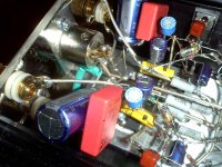
Okay, the blue and the red one are local supply bypass caps (2200u+2u2), the cubic red one is over the 9.1V Zener diode, the yellow one is the 1n cap (C105) and the other two blue caps (C101, C103) are also part of the Aleph CS.
Maybe C102 or setting the AC gain differently would help?
The styroflex I could easily replace with a 10p silver mica, maybe it's a good idea to do so while I'm in there.
Maybe C102 or setting the AC gain differently would help?
The styroflex I could easily replace with a 10p silver mica, maybe it's a good idea to do so while I'm in there.
friend Allen Wright wrote numerous times that those round styroflex caps are good almost as cockroaches
Small wonder i liked the guy.
(and in the FB line, no less)
Ahh, pasta days revisited,nothing like a view right up a cow's pucker.
Attachments
Last edited:
oh
those days of yore .....
nothing better than some olde A , reverted to J input
😉
I'm certainly biased
those days of yore .....
nothing better than some olde A , reverted to J input
😉
I'm certainly biased
Hm, weird. I set the AC current gain to about 61%, and the oscillation is gone (using the 4 Ohm speakers). It was set to 50% before and worked fine with 8 Ohm.
- Home
- Amplifiers
- Pass Labs
- The Mini-A