Well, I have board for both Mini-A and Mini-AX.
You know, I suppose building a aleph-j would be the same.
Just trying to use up these boards. Curious as to how the mini-a and mini-ax would sound with jfets.
You know, I suppose building a aleph-j would be the same.
Just trying to use up these boards. Curious as to how the mini-a and mini-ax would sound with jfets.
Pass DIY Addict
Joined 2000
Paid Member
OK, here is what I was thinking: Using a single pair of J74s as the differential pair for Grey's original version of the Aleph-X (40w output) should work with just a single mosfet per "quadrant" of the schematic. It was when people started paralleling the output devices for higher output power that the gate capacitance of the mosfets started adding up, thus necessitating using multiple pairs of J74s to properly drive the larger output stage.
Now that I've spent a few minutes digging out my schematic for the aleph-mini and looking at it, it seems that this same logic would also work here since there is only a single output device.
A single SJ109 or a pair of matched J74s should work just fine for either amp. The jFets are more linear, so you'll get a bit less midrange and a bit more treble from them than you do from the 9610 devices. One of my large Aleph-X amps has a jFet input and is a rats nest of wires and modifications with parts dangling from wires. I'm thinking about cleaning it up and returning to the 9610 differential.
I would suspect the mini-A with a jfet input would sound very similar to the Aleph-J, just with less power and heat...
already numerous examples how do JFet-ize any size Aleph
easiest with picolo ones , primarily taking in account number of outputs
here is ancient article I wrote here , still useful even if I would write some things little different nowadays
edit : regarding Mini Aleph X - read last posts in Babelfish XJ , or JX …….. or whatever (Aleph X servo for Greedy Boyz)
hard to make it Mini ..... and hardly any benefits , comparing to non-bridged Aleph .......... in fact , when going mini route , there are more steps backwards than forward
Attachments
Last edited:
Pass DIY Addict
Joined 2000
Paid Member
I have a copy of that PDF stashed away - great stuff.
Vince - I don't have any notes about a "mini aleph-x." I guess I always considered that to be Grey's original design with 15v rails, 40w output, and needing two 11"x11"x2" sinks, each with 0.27c/w rating to dissipate 90w of heat per channel.
Vince - I don't have any notes about a "mini aleph-x." I guess I always considered that to be Grey's original design with 15v rails, 40w output, and needing two 11"x11"x2" sinks, each with 0.27c/w rating to dissipate 90w of heat per channel.
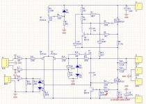
I need some advice regarding a version of the Mini (see schematic).
It's supposed to be fed with a 17V transformer so something like 24V DC (?)

Are FU9210 a good substitute for IRF9610 ?
(Or maybe a must due to higher voltage ?)
Shouldn't R24 and R26 change places ? (see red arrow in scematic)
R9 and R27 have different values, most schematics show same...
... any suggestions ?
Regards from a newbie 🙂
It's supposed to be fed with a 17V transformer so something like 24V DC (?)

Are FU9210 a good substitute for IRF9610 ?
(Or maybe a must due to higher voltage ?)
Shouldn't R24 and R26 change places ? (see red arrow in scematic)
R9 and R27 have different values, most schematics show same...
... any suggestions ?
Regards from a newbie 🙂
got them from ebay , now asking help here ?
anyway , number of parameters are dictated by thermal capacity of case of your choice , same as with rail value
so , what dissipation per channel you're counting on , have you decided what rails you're going to use ...... ?
then we can help , if you start from proper starting position .... 🙂
btw. values of 3W resistors are all wrong ..... we can specify them later
and yes - don't be a cheapskate - buy proper mosfets
better safe than sorry ....... it isn't so much matter of exact type , but of quality - Heaven knows what you got in that kit ........
Thanks 🙂
I have bought 4 IRFP240 and 4 matched IRF9610, but when I discovered that
the amp kit came with a 17V transformer I wasn't shure if I should change anything.
Since the kit is rated 2x10W I thought it had more like a 12V transformer...
I also have Elna Silmics from reliable source so I will change all caps.
The rectifier pcb has only 4 10.000uF caps, so I bought 4 22.000uF
This was going to be a mix of a ready kit, but with my own changes from the info found here.
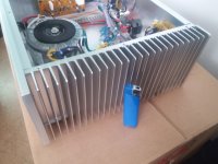
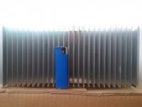
The heat sinks are 10 inches long and 4,5 inches high, the fins protrudes 1,5 inch. Thickness of mounting surface is 0,275 inch. Have no other info about them.
My speakers are rated 4 to 8 Ohms, so if I understand it correctly a higher bias is better in my case. So aim is as high bias as the heatsinks can take 😀
Not sure if this is enough info, so just ask more and I'll try to answer.
Last edited:
you're good up to 40 to 50W of heat per side , maximum
if needed , you can always use Babysitter , in summer days
when you decide what you're going to use for rails , let me know and I'll tell you what value of big resistors to use
if needed , you can always use Babysitter , in summer days
when you decide what you're going to use for rails , let me know and I'll tell you what value of big resistors to use
I get 24,5V out from rectifier board with current transformer.
(+24,5 and -24,5)
It's a bit high for my liking, but this transformer also powers the speaker protection boards, so not easy for me to get a similar.
But if you think is usable I'm all ears. And thanks again I really appreciate it. 🙂
Bias current from 1.2-1.5A if that is possible.
Maybe I should just get rid of the protection boards and get a 12V transformer and live with the "thump".
Last edited:
17Vac will give you something as 21V5 with loaded rectifier/filter block
practically , you count on 1.25 multiplication , not 1.41 , which is for unloaded or lightly loaded conditions
if we stay at 50W of heat as figure for your heatsinks ( and even that , I would say , with necessary use of Babysitter) , that leaves us with 50W/(2 x 21V5)=1A17 ....... which is pretty close to what you want to achieve
for that sort of Iq , put source resistors (R9 and R27) of 0R47/3W , and same value for sense resistor group (R16,R18)
change R11 to 1K , put 100K trimpot in place of R3 ( Iq adjustment)
if you want to have finer setting of output offset , while maintaining desired Iq , replace R25 with 220R (fixed value) and 500R trimpot , both in series
Of course I also would like to thank Mr Pass and GRollins 🙂
Zen Mod: Again looking in the Algar pdf, I see that the psu is similarly designed.
Are the values of resistor (0.5R) and last small capacitor (4.7uF) appropriate for my psu ?
My psu will feed both channels and with 4 22.000uF caps total.
Looking at Algar's feed for Right Channel only, remove C6 and C8.
you're good with "just" 0R1 in CRC
last , small , one - use whatever you have in drawer
considering that you're making "smaller" amp , 88mF is enough
last , small , one - use whatever you have in drawer
considering that you're making "smaller" amp , 88mF is enough
- Home
- Amplifiers
- Pass Labs
- The Mini-A


