I looked it up. The cost is modest, $54 to $75 each, but I like over-design and 10 Amps is the limit which pushes it to the limit. I run my cathode heaters at about 9 Volts when the data sheet says 9 to 11 Volts.9 Volts is supposed to cause the tube to last longer. So does 120 ma, unlike making a spot in the plate glow red hot. Also, if I got someone to hire me to build them a custom amplifier or 833A output stage they could drive preferably with a 45, 2A3 ( which is the same thing as two 45s in parallel ) or a 300B, and a transformer such as a Lundahhl LL2765 or a British made Sowter 5k to 600 Ohms I would consider saving them money by letting them drive it with two car batteries and a dropping resistor of 0.3 Ohms and over-designed 25 Watt rating. Such an arrangement could run two or three hours and be recharged when the amplifier is turned off.
I have not tried SMPS bricks for filaments on directly heated tubes. I do use them to light up series - parallel combinations of odd voltage TV IDH sweep tubes, mostly 24-26 volts and 36 volts. Many SMPS's either will not start up, or try to start then shut down into a cold tube heater.
Big tube heaters look like a dead short when cold, so some margin is needed. 6 X 26 or 36LW6 tubes is about 95 watts when hot. The small squarish Meanwell LRS-150 150 watt units will not reliably start into this load. The larger rectangular RS-150 150 watt units usually do OK.
My UNSET test board uses 2 X 36LW6 tubes. The small LRS-150-36 lights the pair just fine. It will see 4 tubes once the second board is finished. I already know it will not handle 6 tubes.
I doubt that a 100 watt SMPS will reliably start up into a 10 volt 10 amp tube.
Lrt me know if anybody else builds an 833A SET and let me know how the brick sounds. How quite is it? I would be concerned if someone might turn up the Voltage too high by mistake and destroy the tube.
Most of the pre-built SMPS bricks have a limited adjustment range. My 24 volt brick makes just over 26 volts turned up all the way. it is useful for 24, 25 and 26 volt tubes. It will not make 27 volts for 27GB5 / PL500 / PL504 tubes.
The 36 volt one will not go to 33 or 40 volts it will do 35 volts for 35LR6's.
The 36 volt one will not go to 33 or 40 volts it will do 35 volts for 35LR6's.
have you tried smps bricks Magz? 10 volts 10 amp is just 100 watts.....70khz dc ripples are easier to handle than 120hz riples, imho.....and it is outside the audio band to boot...
No I haven't. I did research DC-DC converters for the high voltage supply early on but in the end I decided that I wanted to go with a linear supply for everything, choke input LCLC for everything other than the fan and 6E5P heater. My intention was to see how far I could take that technology in a no-compromise (or at least very few compromise) design.
Maybe some day i might look at the switching alternatives, as they progress in their development.
MIC5156 based linear regulator for fillaments may be what you guys are after for 10-20A of output current. This allows very low dropout voltages, provided you either use the IC with the internal charge pump for the mosfet gate driver, or the MIC5156YM with an auxillary 12V winding for gate drive.
I started work on a board sometime ago, but progress can be slow when you have too many projects.
Just a few pointers, if you ever need to drive a mosfet, LT1010 can be ideal to put between an opamp and the FET capacitances.
I started work on a board sometime ago, but progress can be slow when you have too many projects.
Just a few pointers, if you ever need to drive a mosfet, LT1010 can be ideal to put between an opamp and the FET capacitances.
Last edited:
I've got some experience running the 327A (10.5V, 10.7A filament) with two Meanwell LRS-100-5 stacked. They start reliably within a few seconds and I have run them for many hours at a time with no issue while trying to cook gassy tubes. I'd imagine it would work just as well for an 833A filament, since it is lower power.
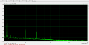
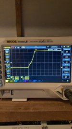
I've also been running the 826, a 7.5V filament tube from a Meanwell RSP-150-7.5 and I cannot detect any detrimental effect in measurements, nor can I hear any (1W distortion measurement attached).
I've also been running the 826, a 7.5V filament tube from a Meanwell RSP-150-7.5 and I cannot detect any detrimental effect in measurements, nor can I hear any (1W distortion measurement attached).
Attachments
Use at least a 200W brick for a 100W load, and a form of real slow soft start to avoid hiccup.
YES.....some 12 volt bricks have voltage adjustments that can be set to 10 volts...
my rule of thumb, no more than 50% of labeled capacity..
Use at least a 200W brick for a 100W load, and a form of real slow soft start to avoid hiccup.
No I haven't. I did research DC-DC converters for the high voltage supply early on but in the end I decided that I wanted to go with a linear supply for everything, choke input LCLC for everything other than the fan and 6E5P heater. My intention was to see how far I could take that technology in a no-compromise (or at least very few compromise) design.
Maybe some day i might look at the switching alternatives, as they progress in their development.
if you buy the right one, you will be rewarded by its efficiency and weight savings...

Thats some serious heavy metal.
Yello - Oh Yeah (Official Video) - YouTube
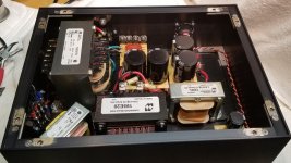
Did you check ripple current rating on the first two snapins before the LC filter? Odds are they dont like over 5-6A each, even for snapins that size. Please dont feel bitten,
Also, i have not read the entire thing, but is that a LT4320 based rectifier ?
Yello - Oh Yeah (Official Video) - YouTube
Did you check ripple current rating on the first two snapins before the LC filter? Odds are they dont like over 5-6A each, even for snapins that size. Please dont feel bitten,
Also, i have not read the entire thing, but is that a LT4320 based rectifier ?
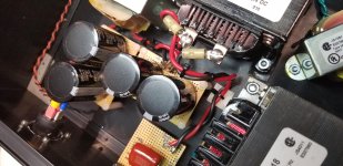
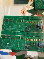
The filament filter is LCLC with the 20A choke before those snap-in caps. See close-up photo below.
The rectifier diodes are 100V, 30A schottkys, VF301005.
All those parts are the same ones that have been inside the amp for the last 7 years, except for the 20A choke which is replacing a 10A unit that was used initially due to size restrictions. Haven't had any issues with them.
The rectifier diodes are 100V, 30A schottkys, VF301005.
All those parts are the same ones that have been inside the amp for the last 7 years, except for the 20A choke which is replacing a 10A unit that was used initially due to size restrictions. Haven't had any issues with them.
Attachments
By the way, my signature line is a quote from the Yello song, The Race.
Yello sounds incredible through these amps and my Infinity RSIIb speakers.
We all know the race is in our heads😀
Heres a regulator i did for 3-10A of output current. Dropout is about 1V
There are some test pics from my phone, i dont have any boards left, tried selling them on the forum but found no takers.
The problem with SMPS is that some poorly designed SMPS flybacks will destroy the secondary diode if the supply overcurrents, or the shunt resistor for the primary switching fet.
Attachments
Cool. After the filter (in the amp box) I use two parallel Colemen regs for the 10A. So far very reliable and very quiet.
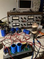
Both amps are complete and operational with their separate filament and heater power supplies. I also swapped in the high dissipation IXYS ISOPLUS247 MOSFETs while I was at it in the 833 cathode regulators. That project is done but I may have stumbled across another modification for the future.
I'm learning more about MOSFETs and I found out that the ones I have been using (including the new ones I just installed) are actually not optimal for a regulator, they are optimized for switching operation - I should have known when there wasn't a safe DC operating area graph in the datasheets. The problem is that these power MOSFETs can fail in DC operation due to the formation of hotspots in the die. A MOSFET optimized for linear operation would have been a better choice.
So..at some point in the future I will most likely be switching the pass MOSFET in the cathode regulators to something like the IXYS IXTX22N100L:
Blocked
which should resolve the failure problems once and for all. In the SOA graph I can see that it is rated for DC operation at more than 1A at 250V, that will accommodate my 160mA idle current plus more grid current than I could possibly throw at it. Live and learn I guess.
For now, the amps are operating just fine and sound as good as ever, with an even quieter background due to the external filament supply, so I'm happy.
Last edited:
L2: Is that 540 whole henries?
I've never heard of partial henries...
It's a Lundahl LL1670 grid choke.
Audio Transformers • Chokes • Lundahl Transformers
In my high Voltage (1000 Volts) plate supplies I use Hammond 193M 10 Henry chokes which I put between polypropylene capacitors on the negative side to ground because these chokes are only pot tested to 800 Volts and I hated putting them inside plastic cages ungrounded. My 10 Volts DC 10 Amps is brute force filtered with 3.5 Farads with a pre-charge system to prevent turn on surge from frying my 50 Amp rated rectifiers and transformer. Your MOSFET regulation system is more sophisticated. I very much like Lundahl transformers, but nobody makes an output transformer as heavy ducty as the Hammond 1642SE pot tested at 3500 Volts and good for 300 ma with the 833A drawing about 125 ma. It has multiple outputs which are perfect for Magnepans with DWM panels added. I wire the two elements of the DWM panels in series at 4 + 4 Ohms to the 8 and 16 Ohm transformer output and keep it in series with the 4 Ohm output for my Magnepan 0.7's (the biggest speakers I can fit in my little Futuro house.
- Home
- Amplifiers
- Tubes / Valves
- The Midlife Crisis - My 833C Amp Build