After a little further research I found a reference with equations for calculating the -3dB point of a source follower from the source resistance (~1kohm for 6E5P triode plus gate stopper) and the MOSFET capacitances, and the low MHz range roll off is exactly to be expected for the above MOSFETs with the 6E5P. Looks like everything is as it should be.
Based on the above results, I think I'll go with the AOT2N60 because of its better thermal performance/higher allowed power dissipation. At full grid current the smaller 1N60 may be pushed beyond its limits, and its lower capacitances don't seem to be a significant advantage in this application.
Based on the above results, I think I'll go with the AOT2N60 because of its better thermal performance/higher allowed power dissipation. At full grid current the smaller 1N60 may be pushed beyond its limits, and its lower capacitances don't seem to be a significant advantage in this application.
small led heatsinks could be used too. after drilling right size hole in centerAn externally hosted image should be here but it was not working when we last tested it.An externally hosted image should be here but it was not working when we last tested it.An externally hosted image should be here but it was not working when we last tested it.
I doubt there is a good reason why they made the original cap like that, your heat sink has too many edges/sharp points which I think are not good for very high voltage.
I doubt there is a good reason why they made the original cap like that, your heat sink has too many edges/sharp points which I think are not good for very high voltage.
Most people over rate coronal discharge. It a couple thousand volts is not as big a problem as you think. A positive and negative would have to be extremely close to each other to arc over at 2kv. Closer then recommended practice. Using those on the plate and grid caps would not pose a serious problem.
Consider where they would be used. And to be honest those led heat sinks would do a more efficient job then the ones made for the purpose. Orientation of the fins is what I'm referring too.
Nick
+1Most people over rate coronal discharge.
one example is car sparkplug, <1mm spark, but several kV
i posted a bit ugly pics of power led coolers, there exist small diameter and nicer
+1
one example is car sparkplug, <1mm spark, but several kV
i posted a bit ugly pics of power led coolers, there exist small diameter and nicer
Ya, like 40,000 volts. Now you can have some corona issues with 40kv. Let me tell ya. Pain in the rear end, LOL.
Most people over rate coronal discharge. It a couple thousand volts is not as big a problem as you think. A positive and negative would have to be extremely close to each other to arc over at 2kv. Closer then recommended practice. Using those on the plate and grid caps would not pose a serious problem.
Consider where they would be used. And to be honest those led heat sinks would do a more efficient job then the ones made for the purpose. Orientation of the fins is what I'm referring too.
Nick
Then I'm curious to why the original cap has horizontal fins instead of vertical.
Anyway it's a bit off topic now.
one example is car sparkplug, <1mm spark, but several kV
A modern auto engine operates at a compression ratio near 10:1. This means that 10 atmospheres of fuel - air mixture is compressed into a space where 1 atmosphere would normally be. This makes that 1mm spark plug gap equal to a 10mm gap, and fuel is a pretty good insulator. We apply a bunch of voltage because we WANT an arc to take place!
Look at the fat intimidating arc a modern ignition system will make into a 1 inch air gap at 1 atm. Then look at the wimpy little spark it makes with a tiny spark plug gap. I always wondered about this until I stopped to think about what is going on inside the cylinder at the moment of ignition.
I agree with the statement that these LED heat sinks are probably OK in this application as long as the environment remains clean. The pointed edges WILL attract dust even at 2500 volts. The dust can absorb moisture.....then bad stuff can happen.
horizontal / vertical fins
Good evening Hoangduongo,
the reason for the fact that the fins are (almost always) horizontal is simple: money ! It is much easier to mill down a piece of metal on a lathe....which gives the horizontal fins.
For optimal heat transfer vertical fins would be much more logical because then convection cooling kicks in (heat rises and draws cooler air from below.....the reason why all heatsinks are in the vertical plane). But....as stated....this is not easy to produce; in any case not as easy as milling/lathe.
Included some examples of vertical fins on 833-topcaps.
On the right you'll see full metal (heavily silvered....blackened) fins; 2 "half moons" clamped together by a spring.
On the left topcap you see some serious industrial stainless steel convection-fins.
Brand unknown....sorry.
I started my amp as a 833-amplifier and used those stainless steel topcaps. Now i switched to the TB3/1000 triode and even after almost 10 years of looking i've only found a single original topcap (far left on picture) so i have a new set made out of red copper. And yes: horizontal fins. I do now have the means to make vertical versions.
Regards,
Reinout
Attachments
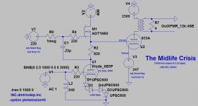
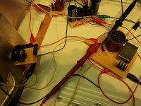
I've been experimenting (OK, playing...) with the clip-leaded "half-amp" over the last two days, and I learned that perhaps shunt regulators don't make the most stable voltage references. Of course I need one under the 833C because I need to hold the voltage and sink a lot of current, but I'm also trying them as the voltage reference for the driver MOSFET (see V7 in the schematic below), and I'm seeing a fluctuation in the output voltage from the MOSFET of 0.3-0.4V when using one regulator and ~1-1.3V for another, not acceptable as that will change the 833 plate current by up to 15mA worst case. Looks like you give up a little voltage stability in exchange for the ability to rapidly react to changing current demands...
So, I worked up a much simpler reference consisting of a cascoded CCS using two 10M90S chips, a 2k adjustment pot and a 47k resistor to ground, with the reference voltage being taken from between the pot and the resistor. Lo and behold, after a 10 minute warmup this thing is rock steady, barely varying by 0.1V! It's also a good bit smaller than the shunt regs and will allow me to free up a little space as well. Of course it can't react to a changing load, but it doesn't need to in that application.
So, I worked up a much simpler reference consisting of a cascoded CCS using two 10M90S chips, a 2k adjustment pot and a 47k resistor to ground, with the reference voltage being taken from between the pot and the resistor. Lo and behold, after a 10 minute warmup this thing is rock steady, barely varying by 0.1V! It's also a good bit smaller than the shunt regs and will allow me to free up a little space as well. Of course it can't react to a changing load, but it doesn't need to in that application.
Attachments
Love the 6E5P but man was it microphonic. The application was a preamp with a step-down output transformer so it might not be an issue in your application.
how much Vp/Vrms this driver gives ? @1V input/max
6E5P mu is about 30, so 1Vp in gives 30Vp out. That's plenty considering the 833C has a mu of 35 itself, it's not hard to drive. For a 2V input, 2*30*35 = 2100V.
Love the 6E5P but man was it microphonic. The application was a preamp with a step-down output transformer so it might not be an issue in your application.
I've dealt with the 26 in my preamp, which can be very microphonic. If I run into issues with that I'll look into mounting the tube socket in a vibration-isolating manner, that seemed to work for the 26.
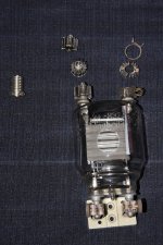
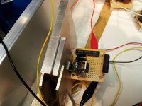
While still waiting on the OPTs, I made up two Vref boards for the driver circuit using the cascaded 10M90S chips feeding a 47K resistor, and upgraded the adjust pot from a Bourns to a Vishay metal foil with a 10ppm/degC tempco. I also put the 2N60 mosfet follower on this board, along with its associated gate stopper and zener protection diodes (picture 1). In this way I can mount the board with the 2N60 using the chassis as a heat sink and save some space while shortening the wiring considerably over the previous version. A small hole in the side of the chassis will allow for adjustment as needed without cracking open the amp. I then tested it in the circuit and all went well; voltage at the 2N60 source (and thus at the 833C grid) rose 2V or so as it warmed up for the first 10 minutes, then became rock solid. Sines and squares look excellent.
So, this simple Vref works much better than the shunt regulator for setting the 2N60 gate voltage, but I still need a stable shunt reg under the 833C...what to do? I contacted Kevin at K&K Audio and after a few emails back and forth he kindly sent me a tiny upgrade board for his shunt regulator that contains a temperature stabilized Vref - I'll be wiring that in and testing it this weekend. Stay tuned.
So, this simple Vref works much better than the shunt regulator for setting the 2N60 gate voltage, but I still need a stable shunt reg under the 833C...what to do? I contacted Kevin at K&K Audio and after a few emails back and forth he kindly sent me a tiny upgrade board for his shunt regulator that contains a temperature stabilized Vref - I'll be wiring that in and testing it this weekend. Stay tuned.
Attachments
The improved, temp compensated Vref from K&K is definitely a better fit for this application when installed in the shunt regulator. After drifting downward steadily (~3V total) during warmup, the voltage was now steady within +/- 0.1V as opposed to fluctuations of up to 1.6V using the non-compensated, simpler stock Vref. Much better for holding the 833C bias steady. Of course the true test will be in the functioning amp itself.
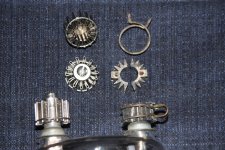
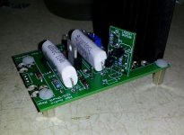
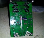
Picture 1 shows the small Vref board installed on the main board, and picture 2 shows the traces I had to cut and the resistor and cap I needed to add in to get the rest of the circuit compatible with the upgrade. I still need to add in a high quality resistor and fine adjustment pot to R9 on the board (on order), for the test I just used an old 1M pot I had to dial in the voltage. The big TO-247 shunt mosfet is mounted off the board so it's not in the picture.
Picture 1 shows the small Vref board installed on the main board, and picture 2 shows the traces I had to cut and the resistor and cap I needed to add in to get the rest of the circuit compatible with the upgrade. I still need to add in a high quality resistor and fine adjustment pot to R9 on the board (on order), for the test I just used an old 1M pot I had to dial in the voltage. The big TO-247 shunt mosfet is mounted off the board so it's not in the picture.
Attachments
Last edited:

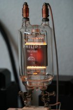
Received a snapshot today from Monolith, this time the powder-coated OPT cans. Next they will pot the OPTs in the cans, let them cure for a few days, and ship them to me, along with the first power supply chokes for the 833 B+.
Anticipation...
Look really small though,
...I meant the tube next to those transformers 😀
The improved, temp compensated Vref from K&K is definitely a better fit for this application when installed in the shunt regulator. After drifting downward steadily (~3V total) during warmup, the voltage was now steady within +/- 0.1V as opposed to fluctuations of up to 1.6V using the non-compensated, simpler stock Vref. Much better for holding the 833C bias steady. Of course the true test will be in the functioning amp itself.
Picture 1 shows the small Vref board installed on the main board, and picture 2 shows the traces I had to cut and the resistor and cap I needed to add in to get the rest of the circuit compatible with the upgrade. I still need to add in a high quality resistor and fine adjustment pot to R9 on the board (on order), for the test I just used an old 1M pot I had to dial in the voltage. The big TO-247 shunt mosfet is mounted off the board so it's not in the picture.
So I replaced the 1M carbon pot in the modified shunt regulator with a 220k Vishay bulk foil resistor plus a 50k Bourne Cermet pot, since I suspected that the lousy temp coefficient of the carbon was not optimal - wow, was I right! Now the shunt reg stabilizes to the set voltage within 15 seconds, and stays there without moving at all. That problem is solved, now I just need to see how it holds up while sinking the 833C cathode current.
Monolith has informed me that my OPTs and HV PS chokes are ready, but unfortunately I'll be traveling next week so I won't be able to pick them up at the airport until the week after. Then it's time to put this bad boy together!
- Home
- Amplifiers
- Tubes / Valves
- The Midlife Crisis - My 833C Amp Build